Building construction road survey unmanned aerial vehicle and use method thereof
A technology of building construction and unmanned aerial vehicles, which is applied in the field of road survey, can solve the problems of high labor intensity and low survey efficiency, and achieve the effect of reducing labor intensity, improving the battery life of the whole machine, and improving survey efficiency
- Summary
- Abstract
- Description
- Claims
- Application Information
AI Technical Summary
Problems solved by technology
Method used
Image

Examples
Embodiment Construction
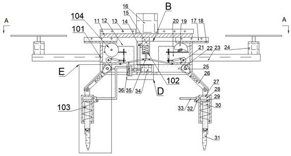
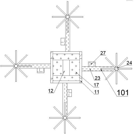
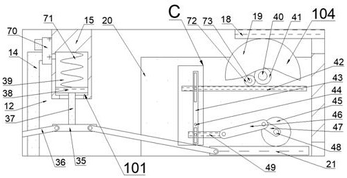
[0027] Combine below Figure 1 to Figure 7 The present invention is described in detail, and for convenience of description, the orientations mentioned below are now stipulated as follows: figure 1 The up, down, left, right, front and back directions of the projection relationship itself are the same.
[0028] A building construction road survey UAV according to the present invention includes a body 11, a storage chamber 12 is provided inside the body 11, four openings are provided on the lower side of the storage chamber 12, and the body 11 is provided with A four-axis aircraft 101, the four-axis aircraft 101 is used to fly to the place to be surveyed and conduct surveys, the storage chamber 12 is provided with a pneumatic mechanism 102, the body 11 is provided with a horizontal support mechanism 103, the horizontal The support mechanism 103 can automatically adjust the posture of the body 11, so that the body 11 can land on different terrains and maintain the horizontal posit...
PUM
 Abstract
Description
Claims
Application Information
 - R&D
- Intellectual Property
- Life Sciences
- Materials
- Tech Scout
- Unparalleled Data Quality
- Higher Quality Content
- 60% Fewer Hallucinations
Browse by: Latest US Patents, China's latest patents, Technical Efficacy Thesaurus, Application Domain, Technology Topic, Popular Technical Reports.
© 2025 PatSnap. All rights reserved.Legal|Privacy policy|Modern Slavery Act Transparency Statement|Sitemap|About US| Contact US: help@patsnap.com