Spinneret plate of melt-blowing mold

A technology of spinneret and mold, which is applied in the direction of spinneret assemblies, textiles and papermaking, etc. It can solve the problems of low output, slow output speed, and increased output of meltblown cloth.

Inactive Publication Date: 2021-06-01
浙江精功机器人智能装备有限公司
View PDF5 Cites 5 Cited by
  • Summary
  • Abstract
  • Description
  • Claims
  • Application Information

AI Technical Summary

Problems solved by technology

[0003] When forming the melt-blown cloth, the spinneret at the output end is only provided with one discharge hole. The discharge speed of the single discharge hole is slow and the output is low. In the market environment where the demand for masks is increasing, it is necessary to consider ensuring Increase the output of meltblown cloth while investing in cost

Method used


Image

  • Spinneret plate of melt-blowing mold
  • Spinneret plate of melt-blowing mold
  • Spinneret plate of melt-blowing mold

Examples


Embodiment

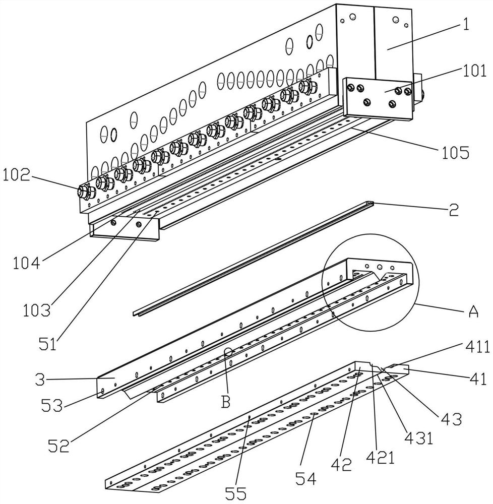
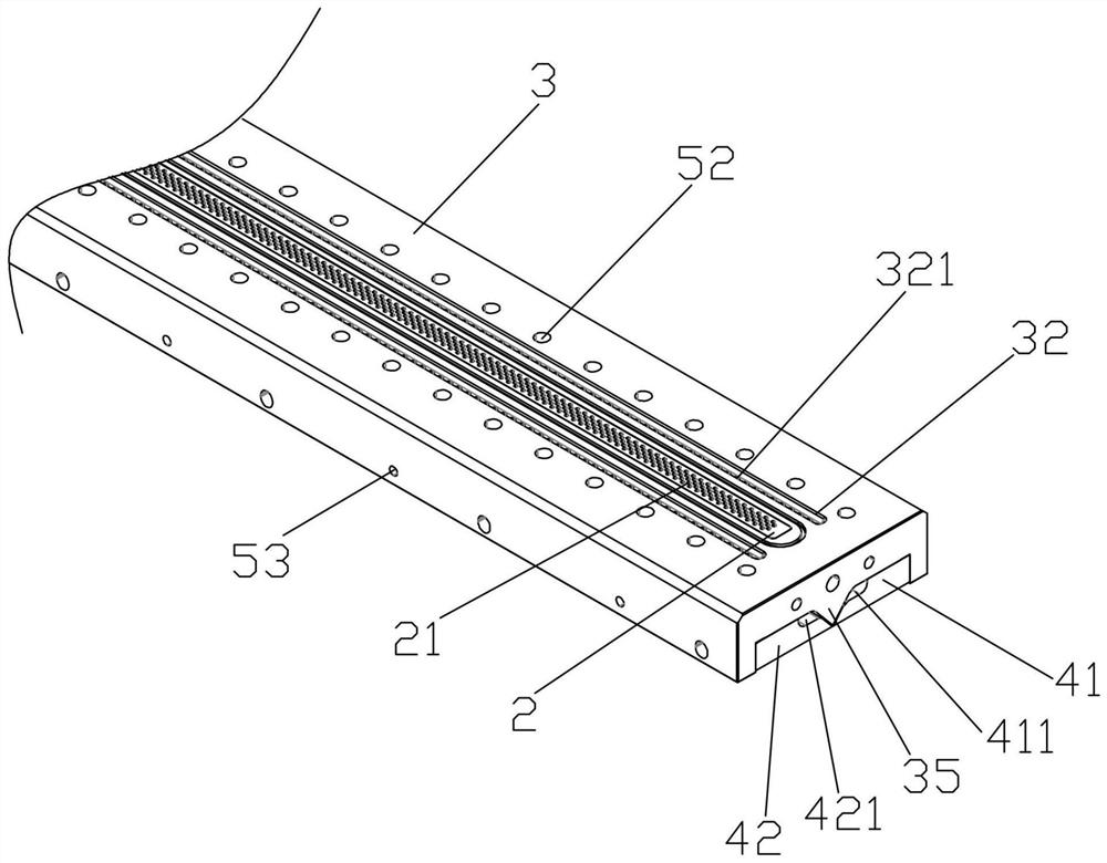
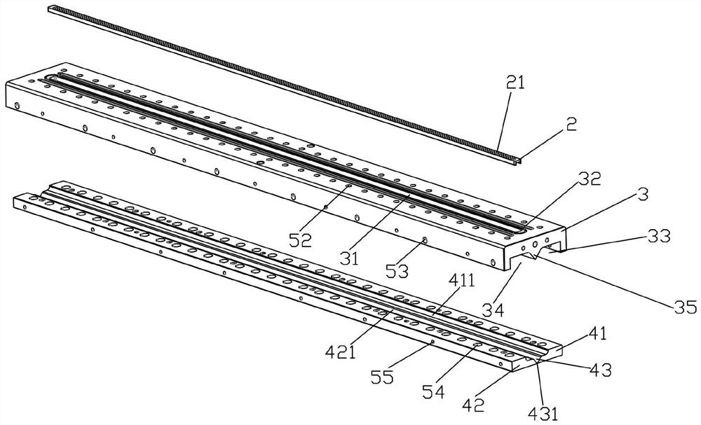
[0021] Embodiment: a kind of spinneret of melt-blown mold, as Figure 1-Figure 7 As shown, it includes a melt blowing mold 1, an injection air pressure device 102 and a fixed plate 101. The fixed plate 101 is connected to the front and rear sides of the melt blow mold 1, and the injection air pressure device 102 is arranged at the bottom of the left and right sides of the melt blow mold 1. The bottom surface of the mold 1 is provided with a material outlet 103 and a plurality of top air outlets 104, and a plurality of top air outlets 104 are respectively arranged on the left and right sides of the material outlet 103, and the top air outlet 104 extends the left and right sides of the material outlet 103. The sides are longitudinally arranged, and the bottom of the melt-blowing mold 1 is provided with a spinneret 3, and the top of the spinneret 3 is provided with a distributing chamber 31 and two through grooves 32, and the distributing chamber 31 and the bottom protruding strip...


PUM

PropertyMeasurementUnit
diameteraaaaaaaaaa

Abstract

The invention discloses a spinneret plate of a melt-blown mold, and belongs to the technical field of melt-blown cloth processing equipment. The spinneret plate comprises a spraying and melting mold, air pressure injection devices and fixing plates, wherein the fixing plates are connected to the front side and the rear side of the spraying and melting mold, and the air pressure injection devices are arranged at the bottoms of the left side and the right side of the spraying and melting mold. The spinneret plate is characterized in that a discharge hole and a plurality of top air outlets are formed in the bottom surface of the spraying and melting mold, and the plurality of top air outlets are formed in the left side and the right side of the discharge hole correspondingly. Left spinneret orifices and right spinneret orifices are formed in the side edges of convex corners of the bottoms of convex strips correspondingly, and the distance between individual orifices of the left spinneret orifices and the right spinneret orifices in each row is 0.65 mm, so that during spinning, the single row of orifices cannot influence one another, the gap of a discharging groove is increased through cooperation of the left spinneret orifices and the right spinneret orifices, the number of sprayed filaments can be effectively increased while the gas is increased, thus the input cost is effectively controlled, and meanwhile, the yield of melt-blown cloth is greatly increased.

Description

technical field [0001] The invention belongs to the technical field of melt-blown cloth production settings, and in particular relates to a spinneret of a melt-blown mold. Background technique [0002] Melt blown cloth is the core material of the mask. The melt blown cloth mainly uses polypropylene as the main raw material, and the fiber diameter can reach 1 to 5 microns. There are many voids, fluffy structure, and good wrinkle resistance. The ultrafine fibers with unique capillary structure increase the number and surface area of ​​fibers per unit area, so that the melt blown cloth has good filterability, shielding, heat insulation and oil absorption. [0003] When forming the melt-blown cloth, the spinneret at the output end is only provided with one discharge hole. The discharge speed of the single discharge hole is slow and the output is low. In the market environment where the demand for masks is increasing, it is necessary to consider ensuring Increase the output of m...

Claims


Application Information

Patent Timeline
Patent Type & Authority Applications(China)
IPC IPC(8): D01D4/02
CPCD01D4/025
Inventor 陈建华王伟苏明东胡春祥
Owner 浙江精功机器人智能装备有限公司
Why Eureka
Try Eureka