Horizontal well buried type continuous coring inner barrel assembly

A horizontal well and coring technology, which is used in the extraction of undisturbed core devices and earthwork drilling, etc., can solve problems such as difficulty in recovering physical properties, difficulty in ensuring core properties, and affecting accuracy.

Active Publication Date: 2021-06-01
NORTHEAST GASOLINEEUM UNIV
View PDF5 Cites 4 Cited by
  • Summary
  • Abstract
  • Description
  • Claims
  • Application Information

AI Technical Summary

Problems solved by technology

However, during the process of coring and pulling out of the drill, the temperature and pressure are released, and the surface is oxidized after contacting the surface gas, the fluid in the core will be volatilized and lost, and the physical properties will be destroyed, which indirectly affects the measurement of oil and gas content and mechanical parameters of the core. The accuracy of results such as pore parameters and pore parameters, and the distortion of measurement data affect the reservoir evaluation and development design of oil and gas resources. Most of the current coring tools can only drill single-segment cores, and are not suitable for multi-segment coring in the same wellbore
At present, in core drilling, the commonly used method of extracting core samples is to obtain multiple cores by continuous tripping, which consumes a lot of manpower and material resources.
Continuous coring can save the waste of resources caused by repeated tripping operations of multi-section coring. However, it is difficult for existing coring devices to guarantee the properties of cores. nature

Method used


Image

  • Horizontal well buried type continuous coring inner barrel assembly
  • Horizontal well buried type continuous coring inner barrel assembly
  • Horizontal well buried type continuous coring inner barrel assembly

Examples


Embodiment Construction

[0026] The present invention will be further described below in conjunction with accompanying drawing:

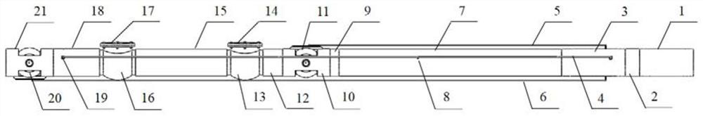
[0027] Depend on figure 1As shown, the high-pressure nitrogen chamber 1 is connected to the upper end of the control assembly 2 through threads, and the lower end of the control assembly 2 is connected to the upper end of the pneumatic cylinder seat 3 through threads. The pneumatic cylinder seat 3 is penetrated by the long rigid connecting rod 6 and the short rigid connecting rod 5, and the air pressure The lower end of the cylinder block 3 is threaded to the upper end of the storage cylinder 7, the cylinder wall of the storage cylinder 7 is provided with a storage cylinder air inlet 8, the lower end of the storage cylinder 7 is threaded to the upper end of the upper sealing ring 9, and the upper sealing ring 9 The lower end is threaded to the upper end of the upper ball valve seat 10, the upper ball valve seat 10 is connected to the upper ball valve 11 by bolts, the lower ...


PUM


Abstract

The invention discloses a horizontal well buried type continuous coring inner barrel assembly. The coring inner barrel assembly comprises a control assembly, a pneumatic cylinder assembly, a high-pressure nitrogen chamber, a curing liquid chamber, a core storage barrel, a ball valve assembly, a check valve, a machining barrel, a core catcher and a high-pressure fluid pipeline, and the pneumatic cylinder assembly is used for controlling a sliding block valve rod to move to complete multiple times of opening and closing of a ball valve, so that continuous coring and sealing are achieved; the check valve is used for sealing the machining barrel and injecting curing liquid to realize burying and sealing of a rock core; the high-pressure nitrogen chamber is used for generating high-pressure nitrogen to impact the rock core to push away a check valve clack and enter the core storage barrel; and the control assembly is used for measuring, feeding back and adjusting the in-situ performance of the temperature and pressure of the core storage barrel, and the procedures are circulated to complete multi-point continuous fidelity coring operation. The coring inner barrel assembly drills down for one time to take out multiple sections of rock cores and conducts buried type sealing processing one by one, so that the coring inner barrel assembly has the characteristic of quality guarantee, nitrogen is filled into the core storage barrel to achieve a pressure maintaining effect, and a heat preservation coating is plated on the inner wall of the core storage barrel to achieve a heat preservation effect.

Description

technical field [0001] The invention relates to the technical field of oil and natural gas drilling and coring, in particular to a horizontal well coring device. Background technique [0002] Drilling and coring technology is the most direct way to obtain cores, which play an extremely important role in oil and gas exploration and development. Through core experiment analysis, it can provide stratigraphic information such as lithology, physical properties, and mineral components for oil and gas exploration and development, as well as understand the stratigraphic properties. Strength, drillability and other indicators, and then guide the implementation of drilling operations and the formulation of development plans. However, during the process of coring and pulling out of the drill, the temperature and pressure are released, and the surface is oxidized after contacting the surface gas, the fluid in the core will be volatilized and lost, and the physical properties will be des...

Claims


Application Information

Patent Timeline
Patent Type & Authority Applications(China)
IPC IPC(8): E21B25/08E21B25/16
CPCE21B25/08E21B25/16
Inventor 王素玲卢秋羽温鹏云李金波李艳春包振山关昕瑶
Owner NORTHEAST GASOLINEEUM UNIV
Why Eureka
Try Eureka