Power generation and refrigeration combined system

A combined system and generator technology, applied in refrigerators, refrigeration components, refrigeration and liquefaction, etc., can solve problems such as poor refrigeration capacity, reduced system output work, and large irreversible losses

Active Publication Date: 2021-06-01
HUNAN UNIV
View PDF5 Cites 2 Cited by
  • Summary
  • Abstract
  • Description
  • Claims
  • Application Information

AI Technical Summary

Problems solved by technology

[0003] At present, the low-grade waste heat recovery and utilization methods that are widely used include single working fluid such as water vapor, carbon dioxide or organic working fluid. This cycle system is due to the phase change of the working fluid in the process of heat absorption by the heat source and heat release by the heat sink. The temperature remains constant, the temperature difference between the corresponding working fluid and the heat source and heat sink is large, and the irreversible loss is large
[0004] In the Kalina cycle using the mixture of ammonia as the working medium, the concentration of the mixture working medium changes during the process of heat absorption by the heat source and heat release by the heat sink, so that the temperature changes accordingly, and the temperature difference between the mixture working medium and the heat source and heat sink Smaller, showing better heat transfer matching characteristics, thereby improving heat transfer performance and reducing irreversible losses, but the working ability of ammonia water is not as good as lithium bromide aqueous solution, and the Kalina cycle cannot provide cold energy
[0005] The Goswami cycle also uses a mixture of ammonia water as the circulating working medium. In the cycle, the superheated ammonia gas expands in the turbine to do work, and the expanded and cooled ammonia gas enters the heat exchanger to absorb heat and refrigerate to provide cold energy. The Goswami cycle By adopting the sensible heat cooling of the exhaust gas of the turbine, the sensible heat of the gas is very small compared to the latent h...

Method used


Image

  • Power generation and refrigeration combined system

Examples


Embodiment Construction

[0039] The invention discloses a combined power generation and refrigeration system to provide refrigeration capacity and ensure that the system does not significantly reduce power generation due to the provision of additional refrigeration.

[0040] The following will clearly and completely describe the technical solutions in the embodiments of the present invention with reference to the accompanying drawings in the embodiments of the present invention. Obviously, the described embodiments are only some, not all, embodiments of the present invention. Based on the embodiments of the present invention, all other embodiments obtained by persons of ordinary skill in the art without making creative efforts belong to the protection scope of the present invention.

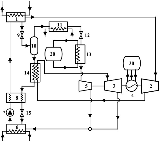
[0041] Such as figure 1As shown, the embodiment of the present invention provides a combined power generation and refrigeration system, including a generator 1, a turbine assembly, a generator 4, an absorber 6, a pump 7,...


PUM


Abstract

The invention discloses a power generation and refrigeration combined system. A generator absorbs a low-grade heat source. An inlet of a turbine assembly is connected with a steam outlet of the generator. A power generator is driven by mechanical energy output by the turbine assembly to operate to generate electric energy and supply the electric energy to electric energy users. An outlet of the turbine assembly is connected with a steam inlet of an absorber. A solution outlet of the absorber is connected with an inlet of a pump, and an outlet of the pump is connected with a solution inlet of the generator. A solution outlet of the generator is connected with an inlet of a first throttle valve. An outlet of the first throttle valve is connected with an inlet of a separator. A steam outlet of the separator is connected with a hot side working medium inlet of a condenser. A hot side working medium outlet of the condenser is connected with an inlet of a second throttle valve. An outlet of the second throttle valve is connected with a refrigerant inlet of an evaporator, and a refrigerant outlet of the evaporator is connected with the steam inlet of the absorber to cool cold energy user fluid. A solution outlet of the separator is connected with an inlet of a third throttle valve, and an outlet of the third throttle valve is connected with a solution inlet of the absorber. The system provides the refrigerating capacity and ensures the generating capacity.

Description

technical field [0001] The invention relates to the technical field of power generation refrigeration equipment, in particular to a combined power generation and refrigeration system. Background technique [0002] In today's energy structure, there are a lot of low-grade waste heat that has not been fully utilized, such as: solar energy, geothermal energy, ocean energy, waste heat in industrial production and waste heat in the operation of thermal power equipment, etc. The waste of these low-grade waste heat further exacerbates environmental pollution and energy crisis. Therefore, it is necessary to adopt an advanced and efficient waste heat recovery system to make full use of this part of low-grade waste heat, thereby reducing the consumption of non-renewable energy, optimizing the energy consumption structure, reducing environmental pollution, and achieving the goal of energy saving and emission reduction. [0003] At present, the low-grade waste heat recovery and utiliza...

Claims


Application Information

Patent Timeline
IPC IPC(8): F25B15/06F25B35/02F25B37/00F25B41/20F25B41/40F25B49/04F01K27/00F01K11/02F01D15/10F01D15/08
CPCF01D15/08F01D15/10F01K11/02F01K27/00F25B15/06F25B35/02F25B37/00F25B49/043F25B2400/14Y02B30/62Y02A30/27
Inventor 张峰廖高良谌冰洁戴幸福
Owner HUNAN UNIV
Why Eureka
Try Eureka