Welding fixing structure and fixing method suitable for adjustable reflector group

A mirror group and fixed structure technology, applied in the direction of installation, optics, instruments, etc., to achieve the effect of good rigidity, easy realization, and strong operability

Active Publication Date: 2021-06-01
西安应用光学研究所
13 Cites 0 Cited by

AI-Extracted Technical Summary

Problems solved by technology

[0005] The purpose of the present invention is to solve the problem of reliable, efficient and low-stress fixed connection between the adjustable mirror group and the mirror frame after the adjustmen...

Abstract

The invention discloses a welding fixing structure suitable for an adjustable reflector group. The fixing structure comprises a reflector group and a reflector bracket (4), the reflector group is coaxially arranged in the reflector bracket (4), a gap is reserved between the reflector group and the reflector bracket (4), the gap is filled with soldering paste, and the reflector group and the reflector bracket (4) are welded and fixedly connected through the soldering paste. According to the invention, the adopted welding fixing mode allows no initial connection between the reflector group and the reflector bracket, so that the reflector group can realize five-dimensional free adjustment in the space by using the adjustment tool, and the overall efficiency of adjustment of the reflector group is further improved; and the common welding process in the electronic assembly industry is creatively improved and is applied to the fixed connection of the light machine assembly, so that the low-stress fixed connection is realized, and meanwhile, the good rigidity of the assembly is ensured.

Application Domain

Mountings

Technology Topic

Electronic assembliesOptics +1

Image

  • Welding fixing structure and fixing method suitable for adjustable reflector group
  • Welding fixing structure and fixing method suitable for adjustable reflector group
  • Welding fixing structure and fixing method suitable for adjustable reflector group

Examples

  • Experimental program(1)

Example Embodiment

[0033]In order to make the objects, content, and advantages of the present invention, the specific embodiments of the present invention will be further described in detail below with reference to the accompanying drawings and examples.
[0034]Aiming at the problems in which the common reflection optical system adjustable the solid-contained structure and the adjustment method, the reliable and low stress connection of the adjustable mirror assembly is fixed, and this embodiment provides an adjustable mirror group. Welding fixing structure and fixing method.
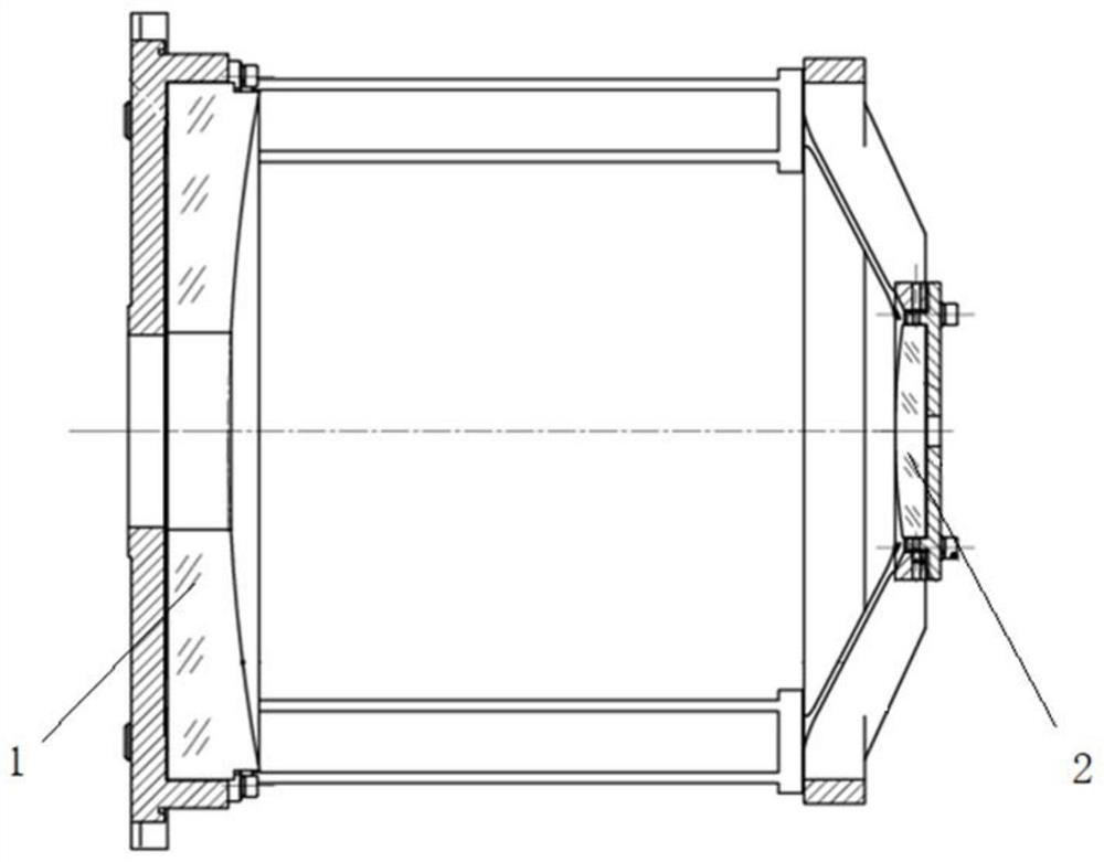
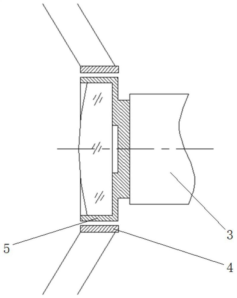
[0035]Such asfigure 1 As shown, it is a triggeric meter system including an adjustable mirror group, including the main mirror assembly 1, which can be adjusted to mirror group 2.figure 2 The schematic diagram of the welding fixing structure of the adjustable reflective mirror group, including the mirror group and the reflective frame 4, and the mirror group coaxial is mounted in the reflective frame 4, and the mirror group is reserved between the mirror group and the reflective frame 4. The clearance, the solder paste is filled in the gap, and the mirror group is solidified by solder paste and the reflective frame 4 welding solids.
[0036]The mirror group includes a mirror frame 5 and a mirror, the mirror frame 5 is a cylindrical shape, and a lens mounting groove is opened on one end surface, and the mirror is mounted in the lens mounting groove; the mirror frame 5 is opened in the outer surface 5-2 A groove 5-1, the groove 5-1 is filled with solder paste.
[0037]The reflective frame 4 includes a thin wall circular hole 4-1, and the mirror frame 5 is inserted into a thin wall round hole 4-1, and the outer surface 5-2 of the mirror frame 5 is welded to the thin-walled round hole 4-1 inner wall surface 4-3.
[0038]The circumference of the thin wall circular hole 4-1 is radially opened with a through hole 4-2 that matches the position of the groove 5-1, and the solder paste in the recess 5-1 is heated by the through hole 4-2.
[0039]The circumferential outer surface 5-2 of the mirror frame 5 is copper-plated with a coating portion to be welded on the inner wall surface 4-3 of the thin-walled circular hole 4-1, and the thickness of the coating is 0.1 mm. The gap between the mirror frame 5 and the reflective frame 4 is 0.6 mm.
[0040]Based on the above-mentioned welding fixing structure, the welding fixing method of the present embodiment includes the following steps:
[0041]Step 1: Fill the low temperature welding solder in the groove of the cylindrical outer surface of the reflective frame, and the mirror group is disposed in the thin-walled circular hole of the reflective frame by adjusting the working frame;
[0042]Step 2: Adjust the spatial position of the reflective mirror group to meet the system requirements, and use the adjustment tool 3 to fix the mirror group position;
[0043]Step 3: Solder paste is heated from the via of the upper half of the reflective frame in the upper half of the reflective frame. Time 3-5 s;
[0044]Step 4: Withdraw the hot air gun, place the temperature of about 10s at room temperature, and remove the connection of the reflective mirror group and the adjustment tool 3.
[0045]Step 5: Rotate the reflective frame 180 degrees, the same as the step 3, 4, and heat the solder paste from the respective vias of the shorter of the reflective frame, and the welding fixation of the mirror set is completed.
[0046]As can be seen from the above technical solution, the problem of fixed-radiography groups in the above-described card system, the present invention proposes a welding fixed type and method suitable for adjustable mirror groups, for a card system, Optimized designing a special structural type secondary frame, and filled with low-temperature soldering paste between the secondary frame and the secondary frame. After the treatment of the mirror assembly was completed, the secondary frame and the secondary frame were performed by the special process method. Welding fixation. This method has a short fixed time, high structural stiffness, low stress, and the like.
[0047]The above is only the preferred embodiment of the present invention, and it should be noted that several improvements and deformations can be made without departing from the technical principles of the invention, these improvements and deformations can be made without departing from the technical principles of the invention. It should also be considered as a scope of protection of the present invention.

PUM

PropertyMeasurementUnit
Thickness0.1mm

Description & Claims & Application Information

We can also present the details of the Description, Claims and Application information to help users get a comprehensive understanding of the technical details of the patent, such as background art, summary of invention, brief description of drawings, description of embodiments, and other original content. On the other hand, users can also determine the specific scope of protection of the technology through the list of claims; as well as understand the changes in the life cycle of the technology with the presentation of the patent timeline. Login to view more.

Similar technology patents

Brewing technology for cooked rice wine

InactiveCN107345184Aimprove overall efficiencyProduct difference is small
Owner:合江县白沙镇燕坪酒厂

Remote sensing image change detection method based on object-level semi-supervised CV model

ActiveCN110070525AImprove learning performanceimprove overall efficiency
Owner:湖北省水利水电科学研究院

L-shaped steel cutting auxiliary tool

Owner:CSSC HUANGPU WENCHONG SHIPBUILDING COMPANY

Vibration dust-removing experiment testing system

InactiveCN104792693Aimprove overall efficiency
Owner:WUHAN INSTITUTE OF TECHNOLOGY +1

Classification and recommendation of technical efficacy words

Why Eureka
Try Eureka