High-performance airborne head-mounted low-light night vision optical system

An optical system, high-performance technology, used in optics, optical components, instruments, etc., can solve the problem of difficult correction of optical system aberrations, and achieve the effect of light weight

Inactive Publication Date: 2021-06-01
湖南航天捷诚电子装备有限责任公司
View PDF5 Cites 2 Cited by
  • Summary
  • Abstract
  • Description
  • Claims
  • Application Information

AI Technical Summary

Problems solved by technology

It can be seen from the formula of image surface illumination that the luminous flux of the optical system is proportional to the square of the relative aperture. In order to improve the luminous flux of the optical system, the relative aperture should be as large as possible, and the corresponding F-number should be as small as possible, but the smaller the F-number, the corresponding Optical system aberrations are more difficult to correct

Method used


Image

  • High-performance airborne head-mounted low-light night vision optical system
  • High-performance airborne head-mounted low-light night vision optical system
  • High-performance airborne head-mounted low-light night vision optical system

Examples


Embodiment Construction

[0025] In order to enable those skilled in the art to better understand the technical solutions of the present invention, the present invention will be further described in detail below in conjunction with the accompanying drawings.

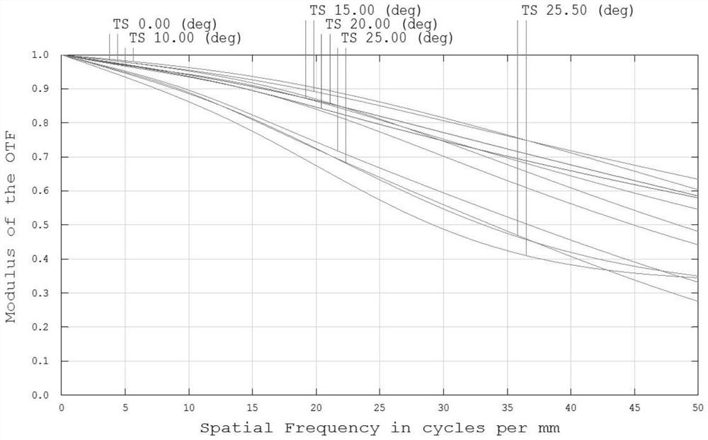
[0026] It should be noted that the MTF evaluation curve represents the relative change of the modulation degree with the spatial frequency (line pair per millimeter, unit: lp / mm) during the imaging process, and is often used to evaluate the resolution of the imaging lens, such as image 3 and Figure 4 As shown, the abscissa in the figure represents the spatial frequency, and the ordinate in the figure represents the degree of modulation (modulus of the optical transfer function).

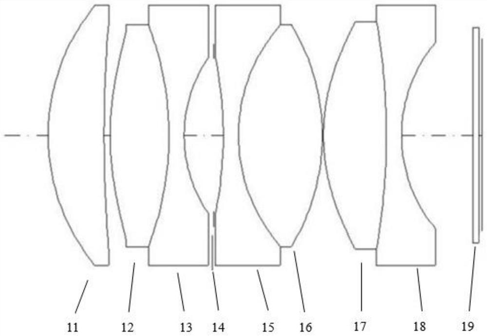
[0027] In this embodiment, the direction of the optical path is from left to right, and "first", "second", and "third" are used to distinguish similar objects, and are not necessarily used to describe a specific order or sequence. It is understood that the data so us...


PUM

PropertyMeasurementUnit
thicknessaaaaaaaaaa
reflectanceaaaaaaaaaa

Abstract

The invention discloses a high-performance airborne head-mounted low-light night vision optical system, which comprises a first meniscus convex lens, a first biconcave lens, a first cemented lens group, a second cemented lens group, a first biconvex lens, a meniscus concave lens, a sensor protection window and an image plane which are sequentially arranged along an optical axis, wherein the first cemented lens group comprises a second meniscus convex lens and a second biconvex lens which are cemented, and the second cemented lens group comprises a third biconvex lens and a second biconcave lens which are cemented. The high-performance airborne head-mounted low-light night vision optical system can achieve fixed focus imaging, the F value is 1.1, the working wave band is 600-1000 nm, the optical system can be compatible with the light-emitting wavelength of optoelectronic equipment in an airborne cabin, and the weight is only 33.6 g; the stray light is weak, a light wave transmission-reflection ratio in the working wave band is as high as 93:7, and the MTF value is not less than 0.5@30lp / mm&25.5 degrees when the optical system is matched with a magnesium alloy mechanical part in an ultra-wide temperature use environment of -40 DEG C to +80 DEG C; the optical resolution is not greater than 1.5 mrad@0.01lx&90% at the position of 2m by matching with a low-light sensor with the sensitivity of 2.5 electrons; and the optical resolution is not greater than 0.8mrad@0.01lx&90% of a contrast target plate at the approximate infinity.

Description

technical field [0001] The invention relates to the field of optical imaging technology, in particular to a high-performance airborne head-mounted low-light night vision optical system. Background technique [0002] In recent years, with the development of low-light sensing technology, combined with optical imaging technology and head-mounted display technology, an interactive feedback information loop is built between the real world, the virtual world and users, and users can enhance perception in low-light environments. The amount of information and understanding of the external scene. The wavelength of the visible light band of the human eye is 380nm-780nm, and the wavelength of natural light at night includes the near-infrared band in addition to the visible light band. The light-sensitive band of the low-light sensor is usually 400nm-1000nm. The working band of the optical system should match that of the sensor, and the luminous flux of the optical system should be inc...

Claims


Application Information

Patent Timeline
Patent Type & Authority Applications(China)
IPC IPC(8): G02B13/00G02B13/18G02B1/11G02B1/10
CPCG02B1/10G02B1/11G02B13/0015G02B13/0045G02B13/006
Inventor 李昀李立松彭超鹏李浩李华
Owner 湖南航天捷诚电子装备有限责任公司
Why Eureka
Try Eureka