
Battery structure for injecting liquid from end part of electrode column and battery liquid injection method

A battery and liquid injection technology, applied in the field of batteries, can solve problems such as inappropriate

Pending Publication Date: 2021-06-01
GUIZHOU ZHONG RUI FENG TAI NEW ENERGY TECH CO LTD
View PDF6 Cites 2 Cited by
  • Summary
  • Abstract
  • Description
  • Claims
  • Application Information

AI Technical Summary

Problems solved by technology

[0009] Therefore, for the technical means currently used for battery liquid injection, it is neither suitable for the liquid injection method of taking out the battery cell alone, nor is it suitable for the method of arbitrarily configuring liquid injection holes at any position on the upper and lower surfaces of the battery for liquid injection.

Method used


Image

  • Battery structure for injecting liquid from end part of electrode column and battery liquid injection method
  • Battery structure for injecting liquid from end part of electrode column and battery liquid injection method
  • Battery structure for injecting liquid from end part of electrode column and battery liquid injection method

Examples


Embodiment 1

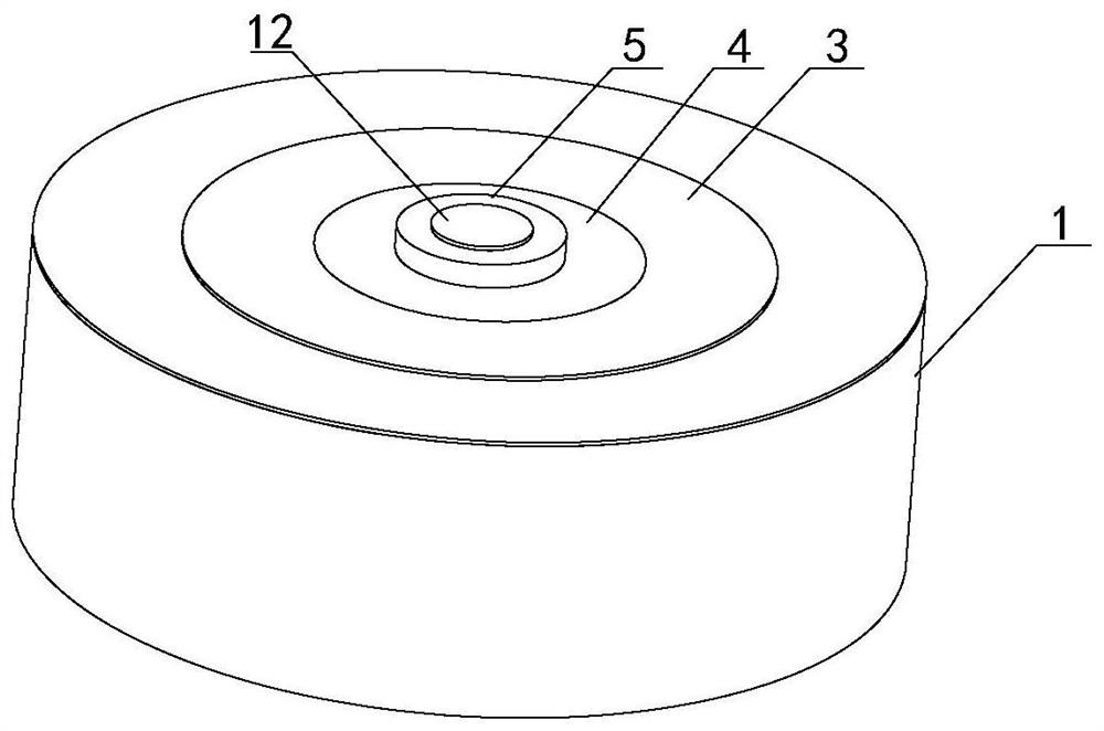
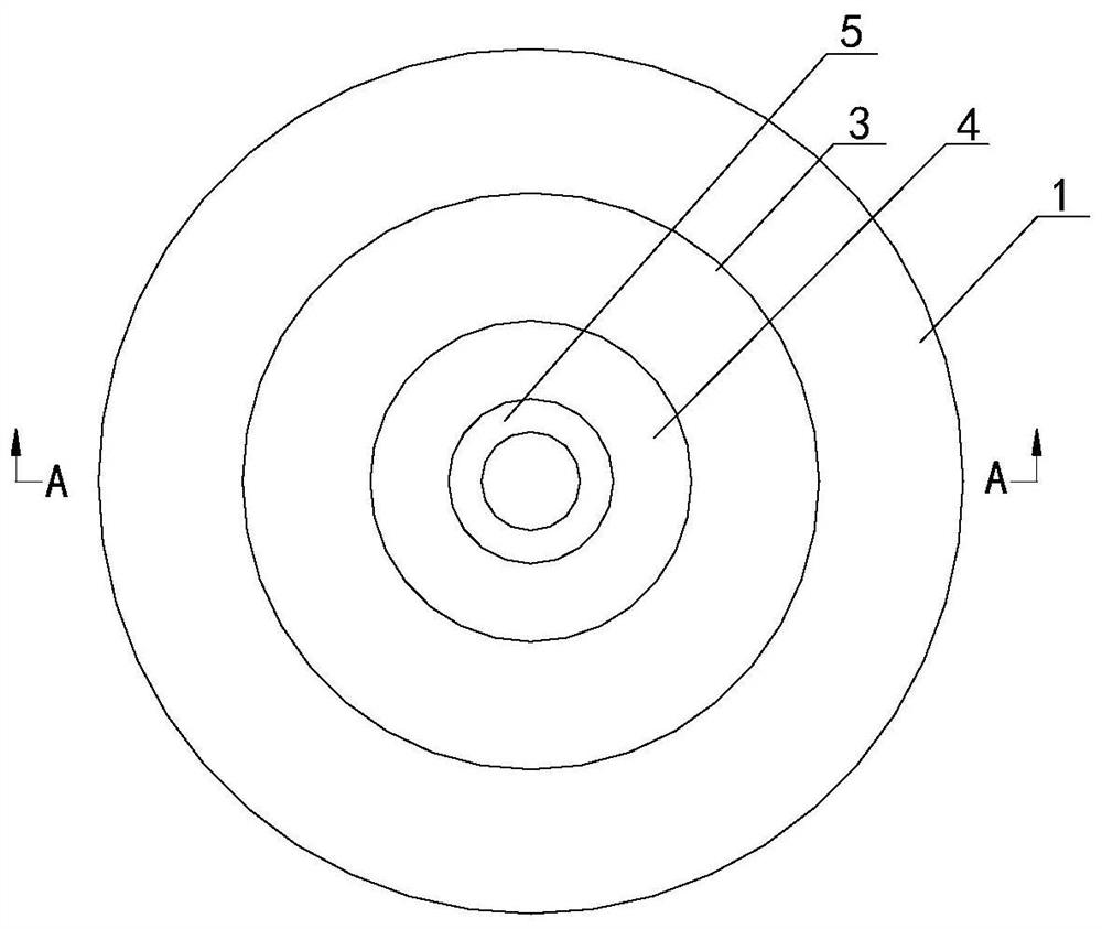
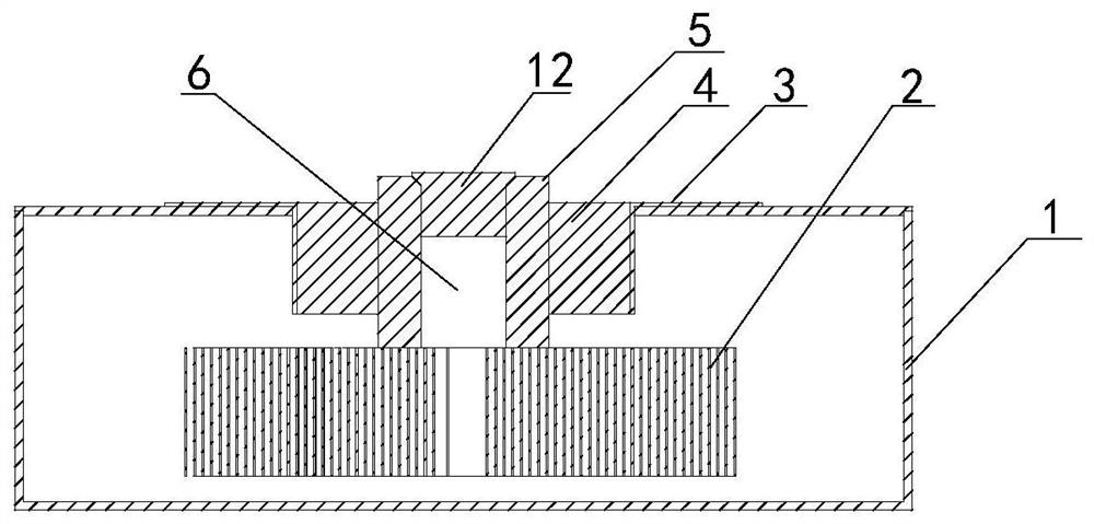
[0053] Such as figure 1 , figure 2 , image 3 , Figure 5 , Figure 7 As shown, the battery structure for injecting liquid from the end of the pole implemented by the technical solution of the present invention includes a battery case 1 with a cylindrical structure, and its interior is set as a hollow structure, so as to be used for assembling the battery cell 2 and containing the injected liquid. electrolyte, the center of the battery cell 2 is equipped with an electrode column 5 with a through hole. Since an opening is provided on the top of the battery case 1, the electrode column 5 can pass through the battery case 1 from bottom to top and extend to the battery. Outside the housing 1, the opening is also used to install the annular metal ring 3 that can seal and fix the assembled battery 2 to a certain extent. The metal ring 3 is close to the top surface of the battery housing 1 and A ring-shaped insulating layer 4 is inserted into the gap between the electrode post 5...

Embodiment 2

[0060] Such as Figure 4 , Figure 6 As shown, the battery structure of injecting liquid from the end of the pole implemented in the second embodiment of the present invention is the supplement and perfection of the technical means implemented in the first embodiment, and under the premise of improving the fluency of the battery liquid injection operation , technicians can further implement corresponding technical means to form corresponding technical solutions, specifically including:

[0061] A technician can add an annular support assembly 7 horizontally on the bottom surface of the inner cavity of the battery case 1. Of course, for the specific material of the support assembly 7, an assembly that has no effect on the performance of the battery cell 2 can be selected. Further, the implemented support assembly 7 There are two layers of diversion supports on the top, and from the inside to the outside are diversion supports one 8 and diversion supports two 9. The cross secti...

Embodiment 3

[0066] Such as Figure 1-5 As shown, Embodiment 3 of the present invention implements a battery liquid injection method, which is a supplement and improvement to the technical means implemented in Embodiment 1 or Embodiment 2. It ensures that the sealing of the battery itself is not damaged and the operation of battery liquid injection is improved. Under the premise of fluency, technicians can further implement corresponding technical means according to the battery structure to form corresponding method steps, specifically including:

[0067] (1) Select the battery to be injected with electrolyte, drill a liquid injection hole 6 through the center of the electrode column 5, and when assembling the battery cell 2 inside the battery, make the middle space area of ​​the battery cell 2 10 pairs Align the liquid injection hole 6 so that the liquid injection hole 6 remains in communication with the middle space area 10;

[0068] (2) Inject the electrolyte solution from the set liqu...


PUM


Abstract

The invention relates to a battery structure for injecting liquid from the end part of an electrode column. The battery surface comprises a battery shell, the surface of the battery shell is only provided with a hole position for assembling the electrode column at the central position of the upper surface; the battery structure comprises the electrode column, a liquid injection hole penetrating through the upper surface and the lower surface of the electrode column is reserved in the electrode column, the upper end of the liquid injection hole is provided with a conical port, and electrolyte is injected into an inner cavity of the battery shell from top to bottom through the liquid injection hole, so that the electrolyte is directly dispersed and guided to each region on the surface of the battery cell through the middle space region of the battery cell from the liquid injection hole; and the battery structure further comprises a conical sealing assembly, which is arranged at the conical port and seals the liquid injection hole. According to the battery structure, only the electrode column is used for configuring the liquid injection hole for liquid injection, and the space at the central position of the internal battery cell is used for improving the fluency of the liquid injection operation of the battery and ensuring the sufficient infiltration of the battery cell, and the stability and the sealing property of the structure of the battery are not influenced.

Description

technical field [0001] The invention relates to the technical field of batteries, in particular to a battery structure and a battery liquid injection method for injecting liquid from the end of a pole. Background technique [0002] Battery liquid injection technology is generally the process of injecting liquid electrolyte into the battery from the liquid injection port. The main purpose is to form ion channels, so as to ensure that the battery has enough lithium ions to migrate between the positive and negative electrodes during the charging and discharging process, realizing reversible cycle. [0003] At present, those skilled in the art know that the common liquid injection methods are mainly divided into two types, one is to directly inject liquid through the liquid injection hole, which is also the most mainstream method, and the other is to put the battery into the electrolyte Let the electrolyte infiltrate into the battery; if the liquid injection hole is used, it ca...

Claims


Application Information

Patent Timeline
Patent Type & Authority Applications(China)
IPC IPC(8): H01M50/636H01M50/627H01M50/543
CPCY02E60/10H01M50/543H01M50/636H01M50/627
Inventor 陈海峰
Owner GUIZHOU ZHONG RUI FENG TAI NEW ENERGY TECH CO LTD
Learn More