Check patentability & draft patents in minutes with Patsnap Eureka AI!

Network service grid arrangement method, device, equipment and medium

A network service and grid technology, applied in the field of network communication, can solve the problems of wasting bandwidth, increasing server computing load, affecting user experience, computing resource consumption, etc., and achieving the effect of low latency

Active Publication Date: 2021-06-01
SUN YAT SEN UNIV
View PDF8 Cites 2 Cited by
  • Summary
  • Abstract
  • Description
  • Claims
  • Application Information

AI Technical Summary

Problems solved by technology

[0006] The above two solutions are based on tunnels to build an overlay network operation service chain on the cluster network. In the cloud data center scenario, it may be necessary to transfer data packets across servers, which may cause data packets to be encapsulated or forwarded multiple times. Waste bandwidth and increase server computing load
With the increase of business volume and SFC scale, it will greatly affect the user experience and the consumption of computing resources
In addition, the service chains created by these two solutions cannot be flexibly configured. They are often strictly limited at the beginning, and the topology structure is relatively simple. Only a simple chain structure can be achieved. As the application scenarios become more complex, The simple chain structure can no longer meet the demand

Method used


Image

  • Network service grid arrangement method, device, equipment and medium
  • Network service grid arrangement method, device, equipment and medium
  • Network service grid arrangement method, device, equipment and medium

Examples


Embodiment 1

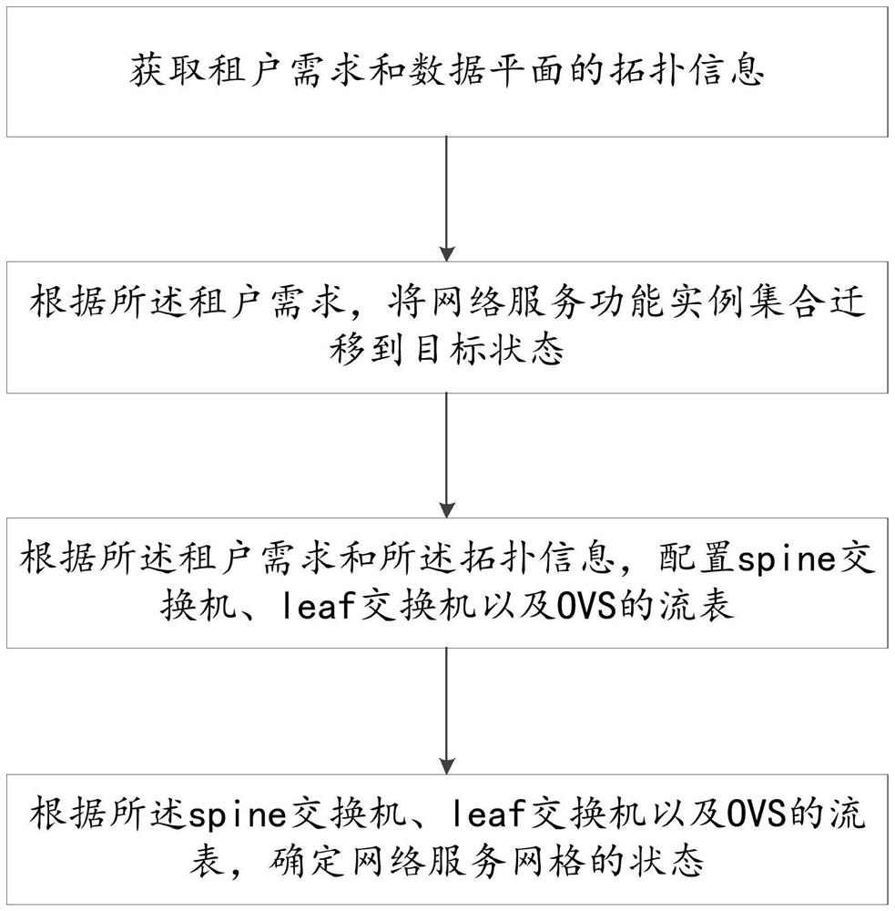
[0087]Exemplarily, the method provided by the example of the present invention may include steps S101-S104 when specifically creating a network service grid:

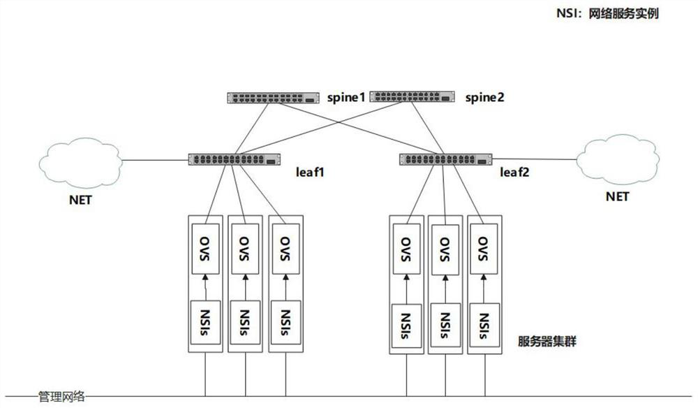
[0088] Optionally, the controller is deployed in the cloud data center in the form of a container, provides services to tenants through the REST API, and has the control authority of the cloud computing platform, which can control the orchestration of network services by the cloud computing platform, and can also control The openflow controller sends flow tables to openflow.

[0089] S101. The tenant logically defines a network service grid according to its actual needs, and sends the definition to the controller through the REST API for processing.

[0090] S102. The controller extracts network service function instances after receiving user requirements, controls the cloud computing platform to orchestrate network services according to the actual deployment of the current cloud data center, and migrates the set of net...

Embodiment 2

[0094] Exemplarily, the specific execution process of changing the network service grid when the network service grid orchestration method provided by the example of the present invention changes according to user requirements may include S201-S205;

[0095] S201. The requirement of the tenant changes, and the original network service function needs to be changed, and the change is uploaded through the REST API interface exposed by the controller.

[0096] S202, same as S102, the controller extracts the required network service function instance, and controls the cloud computing platform to arrange the network service instance to the target state.

[0097] S203. The controller collects state information of the data plane.

[0098] S204. The controller modifies the flow table according to the needs of the tenants and the status information of the data plane. Here, it is necessary to perform the operation of modifying or deleting the old flow table after all the new flow tables ...

Embodiment 3

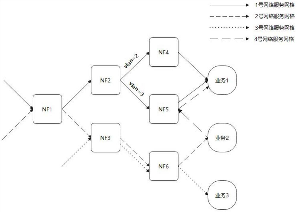
[0101] Exemplary, such as image 3 The illustrated web service mesh logic instance shows the creation of three web service meshes in the data center.

[0102] The forwarding path of No. 1 network service grid is NF1->NF2->[NF4(vlan=2), NF5(vlan=3)]->service 1, and No.1 network service grid generates a branch at SF2, That is to say, the data traffic needs to take different paths after being judged by NF2, so NF2 marks the data packets with different vlan ids. When the data packets arrive at OVS, they will additionally match the vlan information and forward them to different downloads. one jump.

[0103] The forwarding path of Network Service Grid No. 2 is NF1->NF3->NF6->Service 2. Here, Network Service Grid No. 2 and No. 1 share the service of NF1, and the forwarding path of Network Service Grid No. 3 is NF3- >NF6->Service 3, where No. 3 and No. 2 share the sub-network service grid of NF3->NF6. It can be seen that through this system, users can build complex network service ...


PUM


Abstract

The invention discloses a network service grid arrangement method, device, equipment, and a medium. The method comprises the steps of obtaining a tenant demand and topological information of a data plane; migrating a network service function instance set to a target state according to the tenant demand; according to the tenant demand and the topological information, configuring flow tables of a spine switch, a leaf switch and an OVS; and determining the state of the network service grid according to the spine switch, the leaf switch and the flow table of the OVS. According to the method, the cloud native network service grid can be constructed according to the requirements of the tenants, the flexible, low-delay, cross-platform and dynamically-modifiable network service grid is constructed for the user, and the method can be widely applied to the technical field of network communication.

Description

technical field [0001] The invention relates to the technical field of network communication, in particular to a network service grid arrangement method, device, equipment and medium. Background technique [0002] In the process of network communication, various network service functions are included. It can not only include traditional functions such as firewall and NAT, but also include specific network application functions (Service Function). Combining specific network application functions in an orderly manner, and then allowing traffic to pass through these service functions constitutes a Network Service Chain. Generally, in the data center environment, there is often a requirement for the deployment of Network Service Chaining (Network Service Chaining), so that when the message is transmitted in the data center, it can pass through various service nodes to ensure a safe, fast and stable network Serve. [0003] SFC is the abbreviation of Service Function Chain, tha...

Claims


Application Information

Patent Timeline
Patent Type & Authority Applications(China)
IPC IPC(8): H04L12/24H04L12/803H04L12/917H04L47/76
CPCH04L47/125H04L47/76H04L41/145
Inventor 余顺争吴宏
Owner SUN YAT SEN UNIV
Features
  • R&D
  • Intellectual Property
  • Life Sciences
  • Materials
  • Tech Scout
  • Unparalleled Data Quality
  • Higher Quality Content
  • 60% Fewer Hallucinations
Learn More