Wood floor chamfering device for house decoration

A wooden floor and edge chamfering technology, which is applied to wood processing equipment, machine tools suitable for grinding the edge of workpieces, grinding machines, etc., can solve the problems of high labor intensity, time and manpower consumption, and low efficiency, so as to save time and comprehensively Grinding, good grinding effect

Active Publication Date: 2021-06-04
深圳市美置乡墅科技有限公司
View PDF6 Cites 0 Cited by
  • Summary
  • Abstract
  • Description
  • Claims
  • Application Information

AI Technical Summary

Problems solved by technology

[0004] In order to overcome the disadvantages of time-consuming and manpower-consuming, low efficiency and high labor intensity when chamfering wood floors, the technical problem to be solved is: to provide a house that can quickly chamfer wood floors and save manpower Wooden floor chamfering device for decoration

Method used


Image

  • Wood floor chamfering device for house decoration
  • Wood floor chamfering device for house decoration
  • Wood floor chamfering device for house decoration

Examples


Embodiment 1

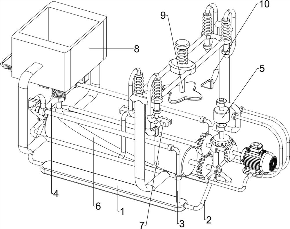
[0068] A wooden floor chamfering device for house decoration, such as figure 1As shown, it includes a base 1, a first support frame 2, a second support frame 3, a fixing mechanism 4 and a polishing mechanism 5, and the left and right sides between the two bases 1 are provided with the first support frame 2, and the two bases 1 The upper right side is equipped with a second support frame 3, the two second support frames 3 are connected with the first support frame 2 on the left side, the first support frame 2 is provided with a fixing mechanism 4, and the right side of the base 1 is provided with a grinding Agency 5.

[0069] When people need to chamfer the wooden floor, people place the wooden floor on the fixing mechanism 4, and then people open the polishing mechanism 5, so that the polishing mechanism 5 rotates, and then people manually move the fixing mechanism 4 to the right, The fixing mechanism 4 drives the wooden floor to move to the right, so that the polishing mecha...

Embodiment 2

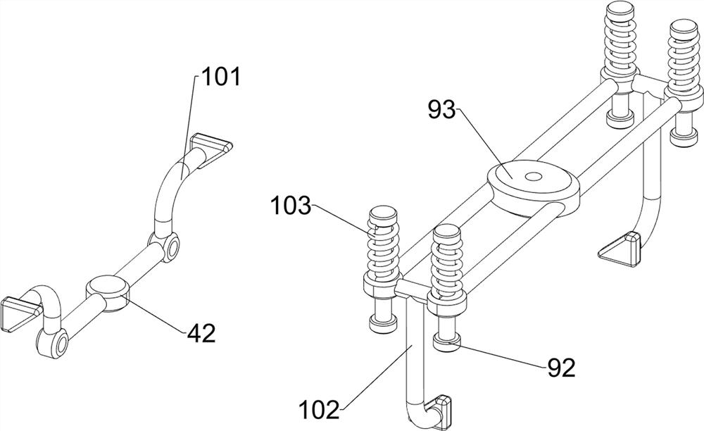
[0071] On the basis of Example 1, such as figure 2 As shown, the fixing mechanism 4 includes a first slide rail 41, a third support frame 42, a first connecting rod 43 and a tray 44, and the front and rear of the first support frame 2 on the left side are provided with the first slide rail 41. A first slide rail 41 is connected with two second support frames 3, a third support frame 42 is slidably provided between the two first slide rails 41, and a first connecting rod 43 is provided in the middle of the third support frame 42 in a rotating manner. , the first connecting rod 43 is provided with a tray 44 .

[0072] When people place the wooden floor on the pallet 44, people will open the grinding mechanism 5, and then people manually move the third support frame 42 to the right, so that the third support frame 42 slides on the first slide rail 41, and then drives The first connecting rod 43 moves to the right, so that the tray 44 moves to the right, so that the wooden floor...

Embodiment 3

[0074] On the basis of Example 2, such as figure 1 , image 3 , Figure 4 , Figure 5 , Figure 6 , Figure 7 and Figure 8 As shown, the grinding mechanism 5 includes a fourth support frame 51, a fifth support frame 52, a sixth support frame 53, a motor 54, a first rotating shaft 55, a second rotating shaft 56, a cutting knife 57 and a bevel gear assembly 58, the right side A fourth support frame 51 is provided between the front and rear ends of the first support frame 2, the fifth support frame 52 is provided on the right side of the fourth support frame 51, and the sixth support frame 53 is provided on the first support frame 2 on the right side. A motor 54 is installed on the fourth support frame 51, the output shaft of the motor 54 is connected with a first rotating shaft 55, the first rotating shaft 55 is connected with the sixth support frame 53 in a rotational manner, and the fifth support frame 52 is rotated between the upper and lower sides. A second rotating s...


PUM


Abstract

The invention relates to a chamfering device, in particular to a wood floor chamfering device for house decoration. The wood floor chamfering device for house decoration can carry out rapid chamfering on wood floors and save manpower. The wood floor chamfering device for house decoration comprises bases, first supporting frames, second supporting frames, fixing mechanisms, and a polishing mechanism, wherein the first supporting frames are arranged on the two sides between the two bases; the second supporting frames are arranged on one sides of the two bases, and the two second supporting frames are connected with the first supporting frames on the side portions; the fixing mechanisms are arranged on the first supporting frames; and the polishing mechanism is arranged on one side of the base. According to the wood floor chamfering device, through mutual cooperation of the fixing mechanisms and the polishing mechanism, a wood floor is fixed through a tray, the wood floor is conveyed and is polished and cut through a cutting knife, and the effect of saving manpower to polish the wood floor is achieved.

Description

technical field [0001] The invention relates to a chamfering device, in particular to a chamfering device for a wooden floor used for house decoration. Background technique [0002] When people decorate the house, there will always be burrs and sharp edges and corners on the wooden boards. Compared with people, it is inconvenient to carry out decoration. Therefore, it is necessary to manually polish the chamfering corners. Currently, there are few equipment for chamfering corners on the market. , so people need to manually polish the wooden floor, and people need to polish the surrounding area of ​​the wooden floor with sandpaper, but the general house needs more wooden floors. It is easier to foam, and the labor intensity is relatively high, and the efficiency is relatively low. [0003] To sum up, it is time-consuming and manpower-intensive when people chamfer the wooden floor, the efficiency is not high, and the labor intensity is relatively high. To design a house decor...

Claims


Application Information

Patent Timeline
Patent Type & Authority Applications(China)
IPC IPC(8): B24B9/18B24B41/06B24B41/00B27C5/00
CPCB24B9/18B24B41/06B24B41/005B27C5/00Y02P70/10
Inventor 张瑛
Owner 深圳市美置乡墅科技有限公司
Why Eureka
Try Eureka