Electrical tree detection characterization method based on microstrip transmission line
A technology of microstrip transmission line and electric branch, which is applied in the direction of measuring electricity, measuring devices, measuring electric variables, etc., can solve the problems of high requirements for experimental equipment, cumbersome experimental steps, and long experimental period, and achieve firm structure, strong applicability, low cost effect
- Summary
- Abstract
- Description
- Claims
- Application Information
AI Technical Summary
Problems solved by technology
Method used
Image
Examples
Embodiment 1
[0025] (1) Microstrip electrode
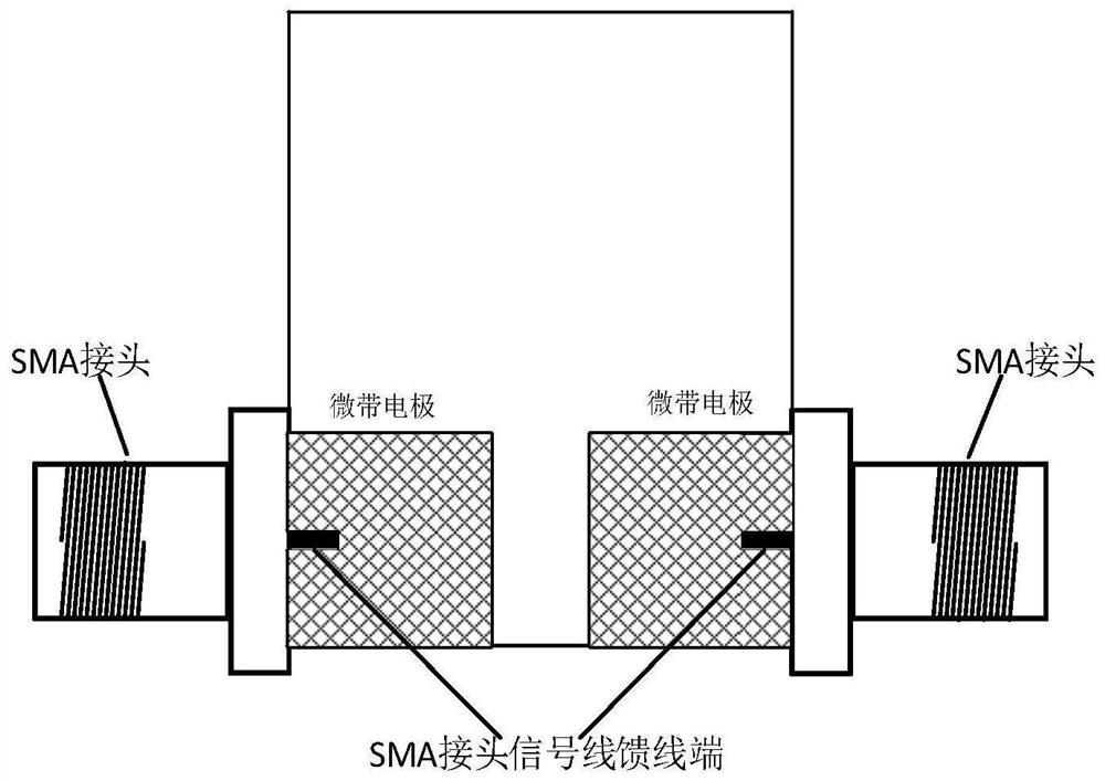
[0026] Prepare square microstrip electrodes with FR4 single-sided copper-clad laminates. The thickness of the copper-clad laminates is 1mm. To facilitate SMA head welding, a 1*0.4mm groove is opened in the middle of the outer side of the two microstrip electrodes. The two microstrip electrodes are located on the same horizontal line, the distance between the microstrip electrodes is 2mm, the overall length is 10mm, and the width is 4mm. In this example, the size of the test fixture is larger to ensure that the tested sample is firmly combined with the test fixture.
[0027] (2) Test fixture
[0028] Weld the feeder end of the signal line of the SMA head to the microstrip electrode for connection with the vector network analyzer during testing. The schematic diagram of the obtained test fixture structure is shown in figure 1 Shown: The grid part is the microstrip electrode, the blank part is the remaining part after the copper is corroded on ...
Embodiment 2
[0035] (1) Microstrip electrode
[0036] Use FR4 single-sided copper-clad laminates to prepare nu-shaped microstrip electrodes. The thickness of the copper-clad laminates is 1mm. The left microstrip electrode is 2mm long and opens a 1*3mm rectangular area upwards, and the right microstrip electrode is 1mm long. 3mm rectangular area. In order to facilitate SMA head welding, a 1*0.4mm slot is opened in the middle of the outer side of the two microstrip electrodes. The two microstrip electrodes are located on the same horizontal line, the distance between the microstrip electrodes is 2 mm, the overall length is 10 mm, and the width is 4 mm. After investigation, it is found that when the width of the tested sample is equivalent to that of the test fixture, the microstrip electrode part does not need a larger size to ensure the stability of the test sample and the test fixture. In order to save costs and simplify the structure of the test fixture, the manufactured test fixture Sm...
Embodiment 3
[0045] (1) Microstrip electrode
[0046] Use FR4 single-sided copper-clad laminates to prepare un-shaped microstrip electrodes. The thickness of the copper-clad laminates is 1mm. The upper side of the left microstrip electrode is 2mm long and a 1*3mm rectangular area is opened downward, and the right microstrip electrode is 1mm long. 3mm rectangular area. In order to facilitate SMA head welding, a 1*0.4mm slot is opened in the middle of the outer side of the two microstrip electrodes. The two microstrip electrodes are located on the same horizontal line, the distance between the microstrip electrodes is 2mm, the overall length is 10mm, and the width is 4mm. After investigation, it is found that when the tested sample is equivalent to the width of the test fixture, the microstrip electrode part does not need a larger size. To ensure the stability of the combination of the tested sample and the test fixture, in order to save costs and simplify the structure of the test fixture,...
PUM
 Abstract
Description
Claims
Application Information
 - R&D
- Intellectual Property
- Life Sciences
- Materials
- Tech Scout
- Unparalleled Data Quality
- Higher Quality Content
- 60% Fewer Hallucinations
Browse by: Latest US Patents, China's latest patents, Technical Efficacy Thesaurus, Application Domain, Technology Topic, Popular Technical Reports.
© 2025 PatSnap. All rights reserved.Legal|Privacy policy|Modern Slavery Act Transparency Statement|Sitemap|About US| Contact US: help@patsnap.com


