
Non-vision-field three-dimensional reconstruction method and system based on analytic signal and compensation reference function

A technology of reference function and signal analysis, applied in the field of non-view 3D reconstruction, it can solve the problems of measurement data easily interfered by secondary echo energy, low reconstruction accuracy, and complicated optical path design, so as to achieve targeted modeling and imaging. The effect of increased speed and accuracy, and increased flexibility

Pending Publication Date: 2021-06-04
XI'AN INST OF OPTICS & FINE MECHANICS - CHINESE ACAD OF SCI
View PDF0 Cites 1 Cited by
  • Summary
  • Abstract
  • Description
  • Claims
  • Application Information

AI Technical Summary

Problems solved by technology

[0006] For the existing non-line-of-sight imaging algorithm, relying on the implementation of non-confocal system, there are problems such as high computational complexity and low reconstruction accuracy, and relying on the implementation of confocal system, the existing optical path design is complicated, and the measurement data is vulnerable to secondary echo. Energy interference and other issues, the present invention provides a non-line-of-sight 3D reconstruction method and system based on analytical signals and compensation reference functions, which can realize simple and fast reconstruction of non-line-of-sight scenes with high precision using a non-confocal system

Method used


Image

  • Non-vision-field three-dimensional reconstruction method and system based on analytic signal and compensation reference function
  • Non-vision-field three-dimensional reconstruction method and system based on analytic signal and compensation reference function
  • Non-vision-field three-dimensional reconstruction method and system based on analytic signal and compensation reference function

Examples


Embodiment Construction

[0056] The present invention will be further described below by means of the accompanying drawings and specific embodiments. The following embodiments are intended to explain the present invention, but should not be construed as limiting the present invention; it should be noted that, for ease of description, only Except for the parts related to the related inventions, the implementation modes and the features in the implementation modes in the present application can be combined with each other under the condition of no conflict.

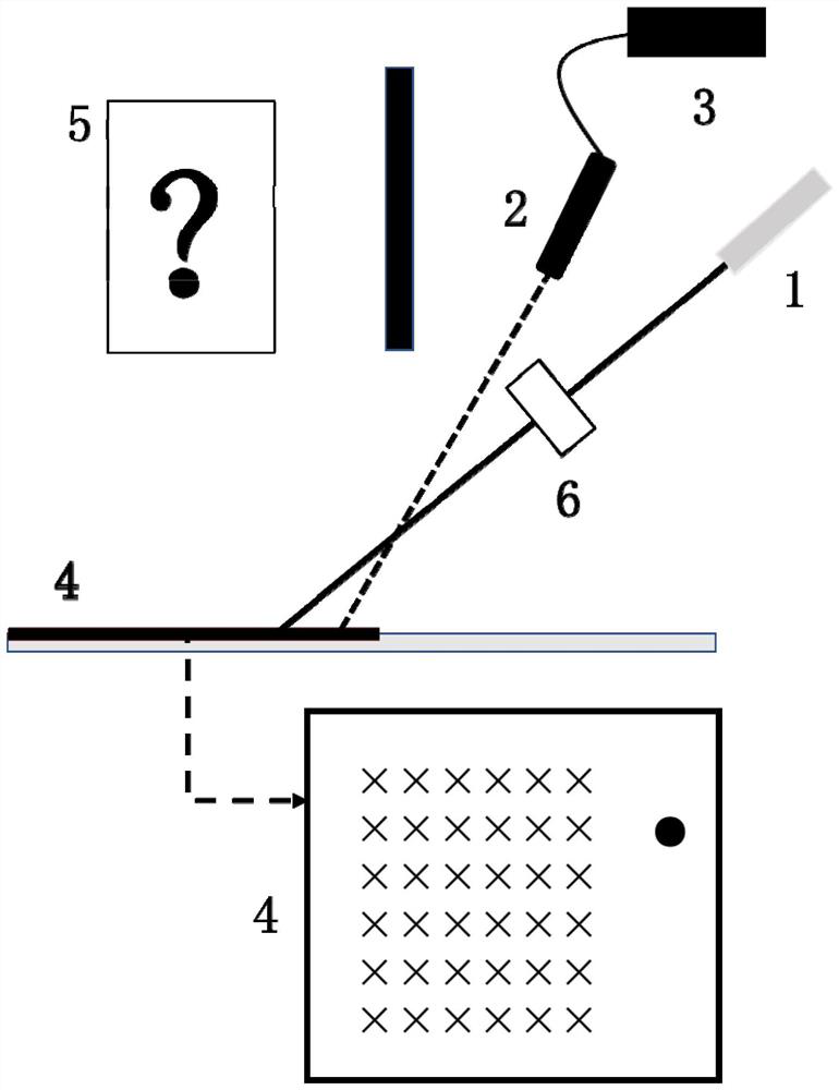
[0057] A non-line-of-sight imaging algorithm of the present invention is used for fast and high-precision imaging of laser non-confocal systems; figure 1 It is a non-line-of-sight imaging system included in a laser non-confocal system, including a pulsed laser 1, a single-photon detector SPAD2, a time-correlated counting module TCSPC3, a reflective interface 4, a target object 5, and a scanning system 6; wherein the pulsed laser 1 A pulse signal of...


PUM


Abstract

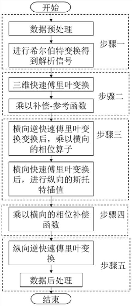
The invention discloses a non-vision-field three-dimensional reconstruction method and system based on an analytic signal and a compensation reference function. In order to overcome the problems that the calculation complexity is too high, the reconstruction precision is not high, the optical path design is complicated, measurement data is easily interfered by secondary echo energy and the like in the existing non-vision-field imaging algorithm, the method comprises the following steps: 1, converting received time-photon data into time-amplitude data, and carrying out Hilbert transform to obtain an analytic signal of the time-amplitude data; 2, performing three-dimensional Fourier transform on the analytic signal, and multiplying the transformed wave number spectrum by a compensation-reference function; 3, after transverse inverse Fourier transform of the wave number spectrum, multiplying the wave number spectrum by a transverse phase operator, and after transverse Fourier transform, carrying out longitudinal Stock interpolation; 4, compensating the wave number spectrum after transverse inverse Fourier transform by using a transverse phase compensation function; 5, carrying out longitudinal inverse Fourier transform to obtain target three-dimensional reconstruction.

Description

technical field [0001] The invention belongs to the field of laser non-line-of-sight imaging, and in particular relates to a non-line-of-sight three-dimensional reconstruction method based on analytical signals and compensation reference functions. Background technique [0002] In recent years, non-line-of-sight imaging technology has developed rapidly. It is a new imaging technology for two-dimensional or three-dimensional reconstruction of scenes outside the observer's visual area. It has good development in complex area detection, vehicle driving assistance, and medical imaging. Foreground: non-line-of-sight imaging mainly uses the time-of-flight data of the secondary echo in the detection area of ​​interest to reconstruct hidden target objects. [0003] The development of non-line-of-sight imaging has gone through several stages. From Kirmani et al., who first proposed the concept of recovering hidden objects based on time-of-flight, Velten et al. used a streak camera as...

Claims


Application Information

Patent Timeline
Patent Type & Authority Applications(China)
IPC IPC(8): G01S17/894G01S7/48G06F17/14
CPCG01S17/894G01S7/4802G06F17/14G06F17/142
Inventor 苏秀琴徐伟豪郝伟
Owner XI'AN INST OF OPTICS & FINE MECHANICS - CHINESE ACAD OF SCI
Learn More