
Bridgeless multi-level rectifier with common direct current bus and control strategy

A common DC bus and multi-level rectification technology, which is applied in the direction of converting AC power input to DC power output, electrical components, and output power conversion devices, can solve the problem of increasing complexity of system topology and control methods, which cannot Using high-voltage direct current transmission, unable to directly connect in series and other problems, to achieve the effects of high overall work efficiency, cost reduction, control complexity, and light weight

Pending Publication Date: 2021-06-04
CHINA UNIV OF MINING & TECH (BEIJING)
View PDF0 Cites 0 Cited by
  • Summary
  • Abstract
  • Description
  • Claims
  • Application Information

AI Technical Summary

Problems solved by technology

However, this type of converter also has obvious disadvantages, which are mainly manifested in: each phase N cascaded rectifier modules will generate N sets of DC output terminals, and because the input terminals are not isolated, the DC output terminals of these N sets of rectifier modules cannot be directly Series connection forms a pair of common high-voltage DC output buses, so it cannot be directly used for high-voltage DC transmission, nor can it be directly connected with multi-level inverter circuits for medium and high voltage frequency conversion speed regulation
In order to realize a common high-voltage DC output bus or realize flexible control of N groups of rectified output DC voltages, N groups of cascaded rectifier modules must be followed by N high-frequency isolated DC-DC conversion modules, resulting in the overall system topology and control mode Increased complexity and decreased productivity

Method used


Image

  • Bridgeless multi-level rectifier with common direct current bus and control strategy
  • Bridgeless multi-level rectifier with common direct current bus and control strategy
  • Bridgeless multi-level rectifier with common direct current bus and control strategy

Examples


Embodiment Construction

[0041] Embodiment and working principle of the present invention are further described below in conjunction with accompanying drawing:

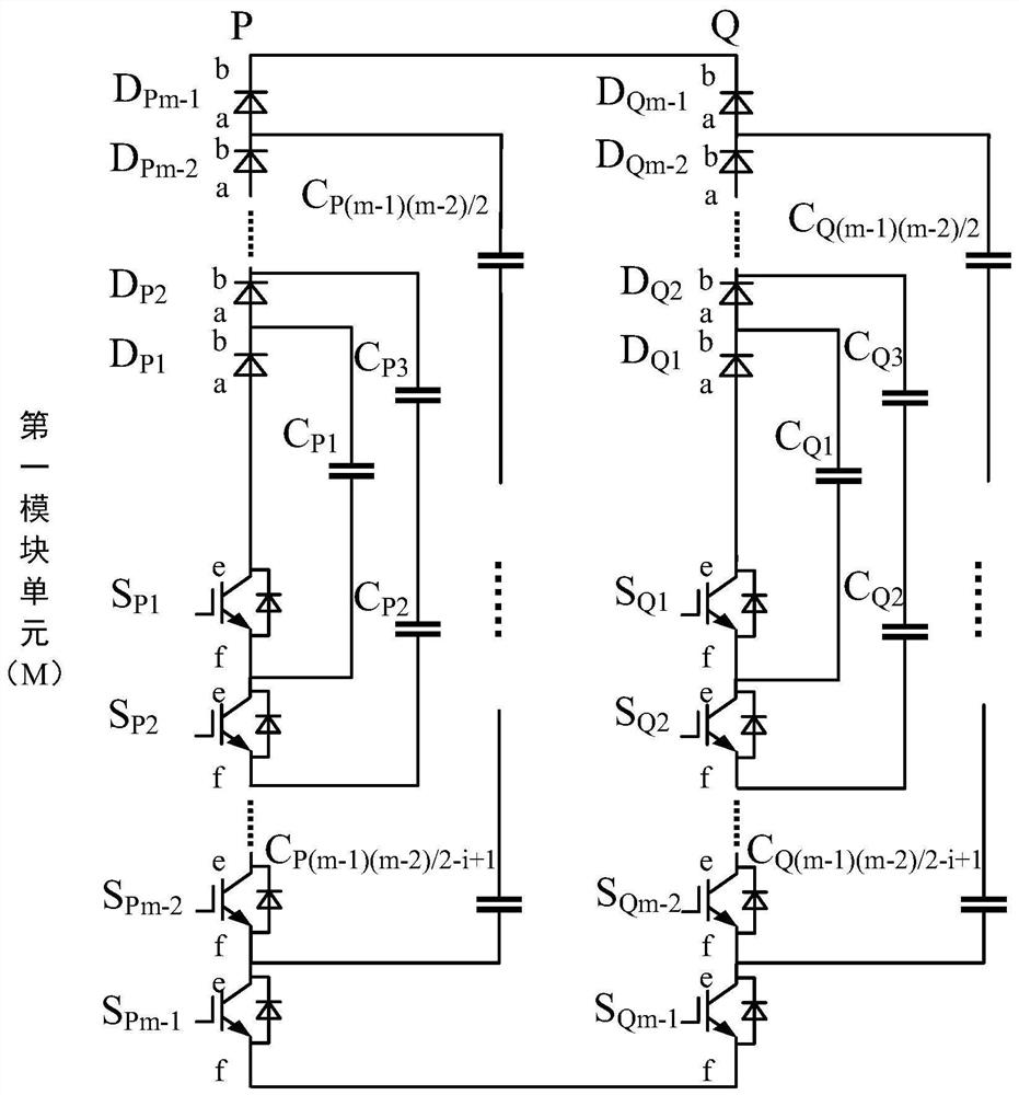
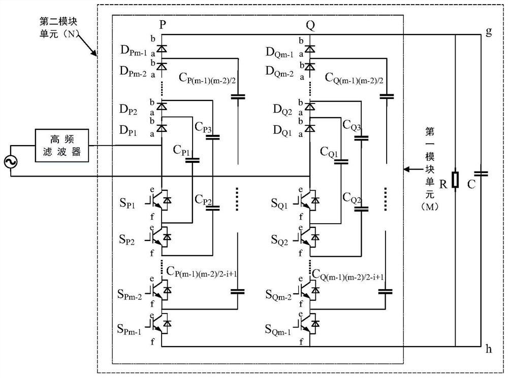
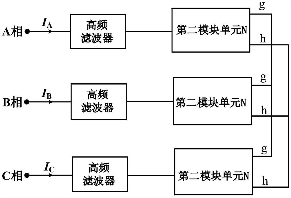
[0042] refer to figure 1 and figure 2 , a bridgeless multilevel rectifier with a common DC bus, including a main power circuit, the main power circuit includes a high frequency filter, a first modular unit (M) of m level (m=2 n -1, where m and n are both positive integers), an output DC capacitor C and a load resistor R, the first module unit (M) includes two first bridge arms P and second bridge arms Q with identical structures, The first bridge arm P includes m-1 switching devices S P1 , S P2 ······S Pm-2 , S Pm-1 , m-1 fast recovery diodes D P1 、D P2 ······D Pm-2 、D Pm-1 , i flying capacitor branch (wherein i=1, 2······m-2), the i-th flying capacitor branch DC capacitor number of the first bridge arm P is i, the first bridge Fast recovery diode D of arm P P1 The second terminal (b) and the fast recovery diode D of the first bri...


PUM


Abstract

The invention discloses a bridgeless multi-level rectifier with a common direct current bus and a control strategy, and belongs to an AC / DC conversion technology and a control technology thereof. A converter provides various main power circuits, each main power circuit is composed of expandable module units and used for forming a pair of public high-voltage direct-current buses, and the defect that high direct-current bus voltage cannot be generated due to voltage stress limitation of a power switch tube is overcome. According to the rectifier and the control strategy thereof provided by the invention, the number of required active power switch tubes is greatly reduced, the cost of the converter and the control complexity are greatly reduced, the balance control of the flying capacitor voltage can be conveniently realized on the basis of obtaining multi-level voltage output, and the expansion of any level number can be flexibly realized. The rectifier has an important application value in the fields of medium-high voltage direct current transmission, high-power medium-high voltage variable frequency speed regulation and the like.

Description

technical field [0001] The invention belongs to the technical field of medium and high voltage frequency conversion speed regulation, and in particular relates to a bridgeless multilevel rectifier with a common direct current bus and a system realization scheme of a control strategy. Background technique [0002] In recent years, "Multilevel Converter" (Multilevel Converter) has been more and more successful in the fields of high voltage and high power frequency conversion speed regulation, active power filtering, high voltage direct current (HVDC) transmission and power system reactive power compensation. Application. The basic circuit topology of traditional medium and high voltage multilevel converters can be roughly divided into clamping type and unit cascading type. At present, the diode clamping produced by Siemens or ABB is widely used in industry Type three-level medium and high voltage inverters, and cascaded H-bridge medium and high voltage inverters produced by Ro...

Claims


Application Information

Patent Timeline
IPC IPC(8): H02M7/217H02M1/32H02J3/26
CPCH02J3/26H02M1/32H02M7/217Y02E40/50
Inventor 程红王聪李瑶璞赵志浩杨道宽李昕于龙飞袁巍李壮
Owner CHINA UNIV OF MINING & TECH (BEIJING)
Learn More