
Clamping device for orthopedic treatment

A clamping device and orthopedic technology, applied in the field of medical equipment, can solve the problems of patients' limbs detached from the splint, limited range of use, cumbersome operation, etc.

Inactive Publication Date: 2021-06-08
四川爱华立康智能科技有限公司
View PDF1 Cites 1 Cited by
  • Summary
  • Abstract
  • Description
  • Claims
  • Application Information

AI Technical Summary

Problems solved by technology

However, it has the following disadvantages: first, the splint cannot fix the limbs in all directions, and it is easy to make the patient's limbs break away from the splint when moving, thereby affecting the operation or treatment; secondly, the existing splint device has a limited contact area, which leads to pressure. It is still relatively large; in addition, the existing fixation methods are mainly bandages or splints, but the contact area between the bandages and the limbs is small. When the patient suffers from pain and struggles, it is easy to strangle the skin, resulting in skin damage. It cannot meet the needs of limb fixation, and if the clamping device needs manual binding, the labor intensity is high, the operation is cumbersome, and the tightness of the binding depends on the strength of the medical staff, which affects the stability of the binding and the clamping is not enough Stable; finally, it needs to be used in conjunction with the hospital bed, it is inconvenient to use alone, and the scope of use is limited

Method used


Image

  • Clamping device for orthopedic treatment
  • Clamping device for orthopedic treatment
  • Clamping device for orthopedic treatment

Examples


Embodiment 1

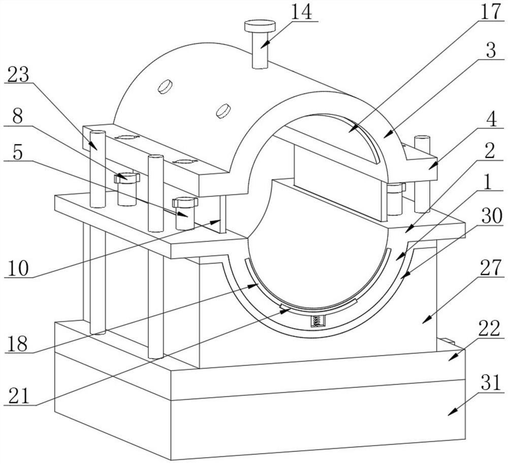
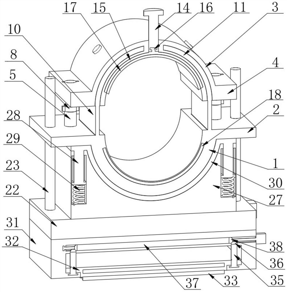
[0036] Refer to attached Figure 1-5 , a clamping device for orthopedic treatment provided by the present invention includes a first splint 1, and first splints 2 are fixedly connected to both sides of the top of the first splint 1, and the first splint 1 and the first splint 2 are integrally formed, and the top of the first splint 1 is provided with a holding mechanism.

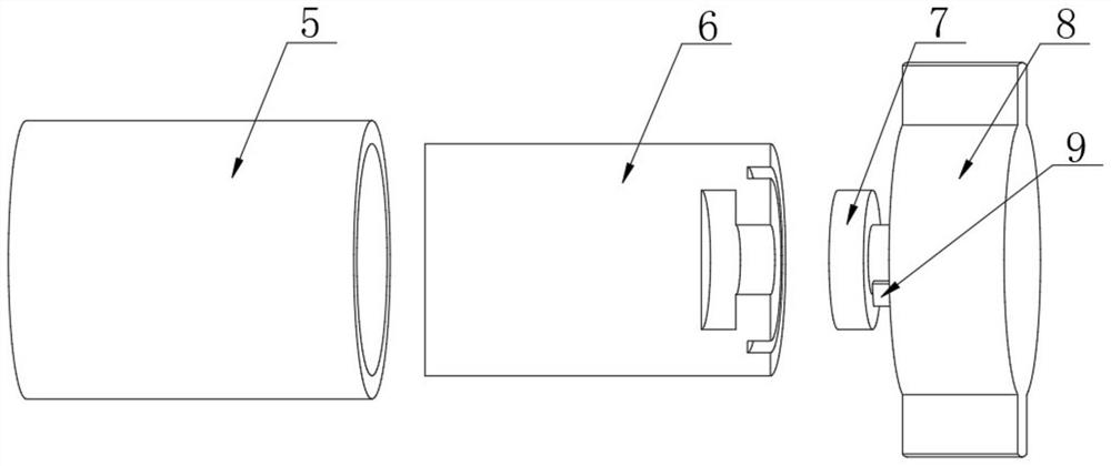
[0037] The holding mechanism includes a second splint 3, the bottom ends of the second splint 3 are fixedly connected with a second fixing plate 4, the second splint 3 and the second fixing plate 4 are integrally formed, and the second fixing plate 4 Both ends of the top are provided with a first special-shaped hole, and both ends of the top of the first fixing plate 2 are fixedly connected with a threaded sleeve 5, and the threaded sleeve 5 is adapted to the first special-shaped hole, and the threaded sleeve 5 is slidably connected with the special-shaped hole. The sliding connection between the second fix...

Embodiment 2

[0043] Refer to attached Figure 6-7 , the clamping device for orthopedic treatment provided by the present invention, the bottom of the first splint 1 is provided with a first fixing sleeve 22, and the inside of the first fixing sleeve 22 is provided with a lifting assembly, and the lifting assembly includes a second screw thread Rod 23, the two ends of the top of the first fixed sleeve 22 are provided with rotating holes, the second threaded rod 23 is located inside the rotating hole and connected with the first fixed sleeve 22 in rotation, and the two ends of the top of the first fixed plate 2 Each end is provided with a second threaded hole, the second threaded rod 23 is arranged inside the second threaded hole and is threadedly connected with the first fixing plate 2, the bottom of the second threaded rod 23 is fixedly connected with the first bevel gear 24, The threaded connection between the second threaded rod 23 and the first fixing plate 2 can effectively drive the f...

Embodiment 3

[0048] Refer to attached Figure 8-9 , the clamping device for orthopedic treatment provided by the present invention, the bottom of the first fixed sleeve 22 is fixedly connected with the second fixed sleeve 31, and the second fixed sleeve 31 is provided with a moving assembly inside, and the moving assembly includes a sliding Cover 32, the bottom of the second fixed sleeve 31 is provided with a third sliding groove 34, the sliding sleeve 32 is located inside the third sliding groove 34 and is slidably connected with the second fixed sleeve 31, the sliding sleeve 32 can slide in the third Sliding up and down in the groove 34, the bottom of the sliding sleeve 32 is fixedly connected with a fixed shaft, the outside of the fixed shaft is provided with a roller 33, and the roller 33 is arranged on the outside of the fixed shaft and is movably socketed with the fixed shaft. Roller wheels 33 are provided at the bottom to effectively control the movement of the device.

[0049] Fur...


PUM


Abstract

The invention discloses a clamping device for orthopedic treatment which comprises a first clamping plate, first fixing plates are fixedly connected to the two sides of the top of the first clamping plate, and a clamping mechanism is arranged at the top of the first clamping plate. The clamping mechanism comprises a second clamping plate, second fixing plates are fixedly connected to the two ends of the bottom of the second clamping plate, first special-shaped holes are formed in the two ends of the top of each second fixing plate, threaded sleeves are fixedly connected to the two ends of the top of each first fixing plate, threaded blocks are in threaded connection with the interiors of the threaded sleeves, first rotating grooves are formed in the tops of the threaded blocks, first connecting blocks are arranged in the first rotating grooves, first special-shaped blocks are fixedly connected to the top of the first connecting blocks, and the first special-shaped blocks are arranged in the first special-shaped holes and movably connected with the second fixing plates in a sleeving mode. The clamping device has the advantages that the problem that an existing clamping device is prone to unstable clamping or limbs of a patient are prone to being separated from clamping plates during clamping can be solved, and the patient can be effectively prevented from being injured by clamping, which facilitates smooth operation or treatment.

Description

technical field [0001] The invention relates to the technical field of medical instruments, in particular to a clamping device for orthopedic treatment. Background technique [0002] In the field of orthopedics, operations or treatments such as limb dislocation, fracture, and bone cutting are often performed. During the operation or treatment, it is necessary to fix the patient's limbs to ensure the smooth progress of the operation or treatment. The existing fixation methods are mainly fixed by manual pressing and strapping. Manual pressing is labor-intensive and poor in stability, which may easily lead to secondary injuries of patients. Although strapping is less labor-intensive, the binding of straps and limbs The contact area is small and the pressure is strong, which is not conducive to blood circulation, easily causes bruises, damages the skin, etc., and cannot well meet the needs of limb fixation. [0003] Chinese patent CN202069736U discloses a splint for orthopedic ...

Claims


Application Information

Patent Timeline
IPC IPC(8): A61B90/14A61G13/12
CPCA61G13/1235A61G13/1245A61G13/1285A61G2210/10A61G2210/90A61B90/14
Inventor 杜平
Owner 四川爱华立康智能科技有限公司
Learn More