Thread trimming presser foot lifting mechanism of sewing machine and sewing machine

A technology of thread trimming mechanism and presser foot lifting, which is applied in the direction of thread cutting mechanism, cloth pressing mechanism, sewing machine components, etc. in the sewing machine, which can solve the problems of high control precision and complex structure, and achieve the requirement of reducing control precision and making it more convenient. Effects of control, simplification and manner of control

Active Publication Date: 2021-06-08
ZHEJIANG MAQI SEWING MACHINE
View PDF7 Cites 0 Cited by
  • Summary
  • Abstract
  • Description
  • Claims
  • Application Information

AI Technical Summary

Problems solved by technology

[0003] Aiming at the shortcomings of complex structure and high control precision requirements in the prior art, the present invention provides a sewing machine thread trimmer lifting mechanism and sewing machine with simple structure and low control precision requirements

Method used


Image

  • Thread trimming presser foot lifting mechanism of sewing machine and sewing machine
  • Thread trimming presser foot lifting mechanism of sewing machine and sewing machine
  • Thread trimming presser foot lifting mechanism of sewing machine and sewing machine

Examples


Embodiment 1

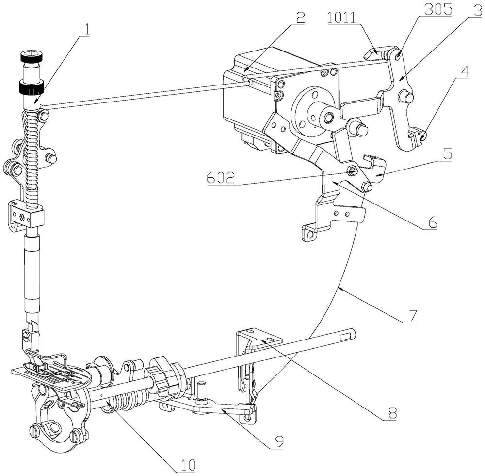
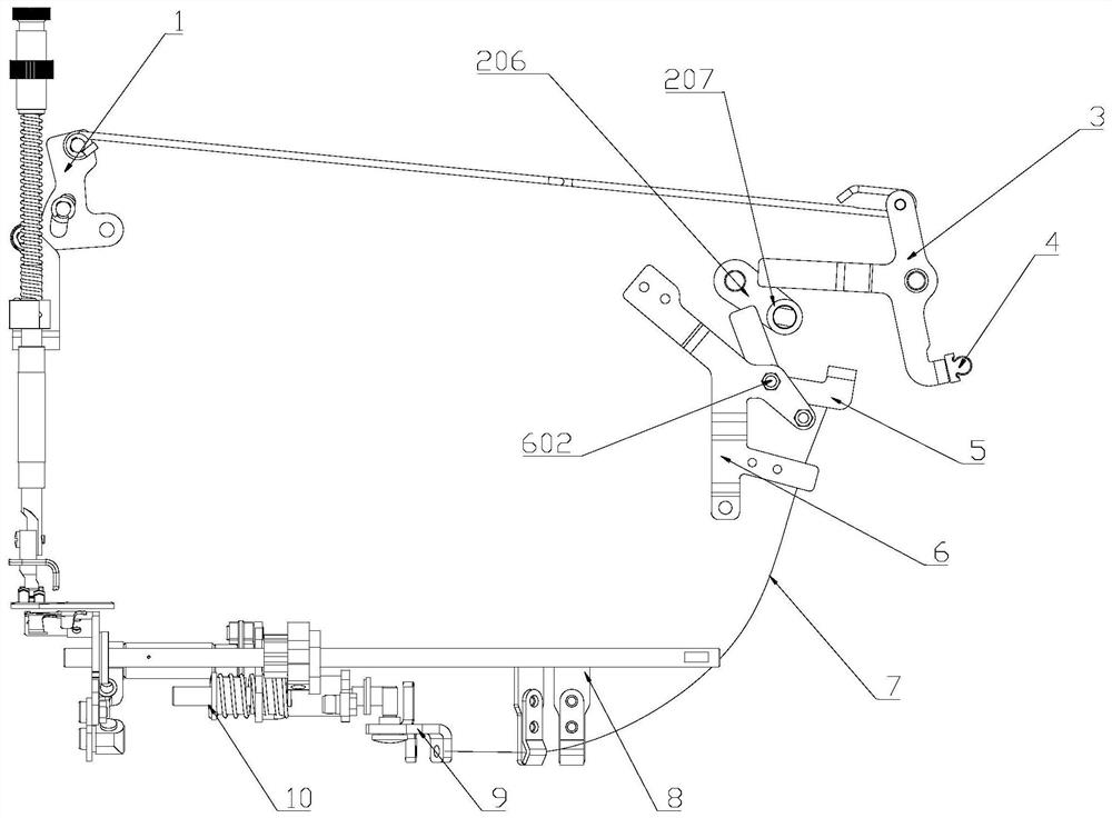
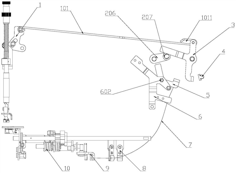
[0047] Thread trimming and presser foot lifting mechanism of sewing machine, such as Figure 1 to Figure 15As shown, it includes a drive assembly 2 and a presser foot lifting mechanism 1 and a thread trimming mechanism 10 driven by the drive assembly 2. Both the presser foot lifting mechanism 1 and the thread trimming mechanism 10 are in the prior art, and also include an upper swing lever 3 and a lower swing lever. Rod 5, the upper swing rod 3 is connected with the presser foot lifting mechanism 1 through the pull rod 101, the lower swing rod 5 is connected with the thread trimming mechanism 10 through the steel rope assembly 7 and the thread release seat 9, and the driving assembly 2 drives the upper swing rod 3 and the lower swing Rod 5 swings. The drive assembly 2 includes a drive motor 201, a crank 206 with one end sleeved on the motor shaft 209 of the drive motor 201, and a roller 207 connected to the other end of the crank 206. The upper swing lever 3 and the lower swin...

Embodiment 2

[0054] Thread trimming and presser foot lifting mechanism of sewing machine, such as Figure 1 to Figure 15 As shown, on the basis of Embodiment 1, the driving assembly 2 also includes a rear window panel 202, a rear window panel pad 203, an oil seal 204 and a fixing sleeve 205, and the driving motor 201 is fixed on the rear window panel 202 and the driving motor 201 The motor shaft 209 of the motor runs through the rear window panel 202, the oil seal 204 and the fixed sleeve 205 are sleeved on the motor shaft 209 of the driving motor 201, the oil seal 204 is arranged in the fixed sleeve 205, and the rear window panel gasket 203 is arranged on the fixed sleeve 205 and the rear window panel. Between the window panels 202 , the fixed sleeve 205 is fixedly installed on the rear window panel pad 203 , and the lower end of the fixed sleeve 205 is provided with an oil return hole 210 . The rear window plate 202 and the rear window plate pad 203 are fixedly connected with the machine...

Embodiment 3

[0058] a sewing machine such as Figure 1 to Figure 15 Shown, comprise the thread trimmer lifter foot mechanism of above-mentioned sewing machine.

[0059] In the initial state, the lower end of the stopper 304 of the upper swing lever 3 abuts against the rubber pad 4 on the machine head 11. At this time, the presser foot lifting mechanism 1 is in the downward pressing state; the second resistance portion 503 of the lower swing lever 5 Abut against the limit post 12 on the bracket 6; the drive shaft 1001 of the thread trimming mechanism 10 is against the drive shaft 1001 of the thread release seat 9 and push the third resistance part 903 of the thread release seat 9 to rotate to the limit in the direction of the steel rope 701 position, so that the thread trimmer head 11 cannot trigger the thread trimming action. The motor shaft 209 of the driving motor 201 is located between the first power part 301 and the second power part 501 , and neither the first power part 301 nor the...


PUM


Abstract

The invention relates to the technical field of sewing machines, and discloses a thread trimming presser foot lifting mechanism of a sewing machine and the sewing machine. The thread trimming presser foot lifting mechanism comprises a driving assembly (2) as well as a presser foot lifting mechanism (1) and a thread trimming mechanism (10) driven by the driving assembly (2), and further comprises an upper swing rod (3) and a lower swing rod (5), wherein the upper swing rod (3) is connected with the presser foot lifting mechanism (1) through a pull rod (101); the lower swing rod (5) is connected with the thread trimming mechanism (10) through a steel rope assembly (7) and a thread loosening seat (9); the driving assembly (2) comprises a driving motor (201), a crank (206) of which one end sleeving a motor shaft (209) of the driving motor (201), and a roller (207) connected with the other end of the crank (206); the upper swing rod (3) comprises a first power part (301); the lower swing rod (5) comprises a second power part (501); and the roller (207) swings between the first power part (301) and the second power part (501). According to the invention, the control structure and the control mode are simplified.

Description

technical field [0001] The invention relates to the technical field of sewing machines, in particular to a thread trimming and presser foot lifting mechanism of the sewing machine and the sewing machine. Background technique [0002] At present, it is gradually becoming a trend for stepping motors to control thread trimming and presser foot lifting, but almost all stepping motors are placed under the bottom plate, and therefore it is necessary to configure a sealed oil pan and modify the structure of the existing bottom plate. And because most of them adopt the cam structure, the requirements for the dimensional accuracy of the parts and the electronic control system are also relatively high. For example, the publication number is: CN 104878529 A discloses a thread trimming and presser foot lifting device for a sewing machine, which includes a stepping motor, a fork mechanism and a cam; A fixed ring, one end of the driving rod is fixed on the main shaft of the stepping moto...

Claims


Application Information

Patent Timeline
Patent Type & Authority Applications(China)
IPC IPC(8): D05B29/02D05B65/02D05B69/12
CPCD05B29/02D05B65/02D05B69/12
Inventor 颜慧军何清
Owner ZHEJIANG MAQI SEWING MACHINE
Why Eureka
Try Eureka