A Construction Method for Filling Wall Foundation with Deep Backfilling Soil

A technology for foundation construction and backfilling, which is used in foundation structure engineering, sheet pile walls, earthwork drilling, etc. It can solve the problems of affecting the introduction of steel pipe piles, cannot be effectively exported, and residual soil and stone, so as to improve the ability to carry soil and stone. , Reduce the sidewall soil and stone falling, reduce the effect of falling

Active Publication Date: 2022-03-25
温州城建集团股份有限公司
View PDF8 Cites 0 Cited by
  • Summary
  • Abstract
  • Description
  • Claims
  • Application Information

AI Technical Summary

Problems solved by technology

[0004] But in the prior art, after completing a drilling, it is necessary to export the auger bit. When the auger bit is exported, it can take out the earth and rocks, and then rotate or vibrate the auger bit outside the pile hole to make the earth and rock fall. Because the helical blade structure of the auger bit is helical, soil and rocks can easily slip off the surface of the helical blade, and a large amount of crushed soil and rocks inside the pile hole remain and cannot be effectively exported, which affects the introduction of steel pipe piles in the later stage. During the process, the soil and rocks on the side wall of the pile hole will also continue to fall due to the collision of the auger bit, and the side wall of the pile hole is not fully squeezed, which is prone to problems such as adduction or collapse of the pile hole

Method used


Image

  • A Construction Method for Filling Wall Foundation with Deep Backfilling Soil
  • A Construction Method for Filling Wall Foundation with Deep Backfilling Soil
  • A Construction Method for Filling Wall Foundation with Deep Backfilling Soil

Examples


Embodiment approach

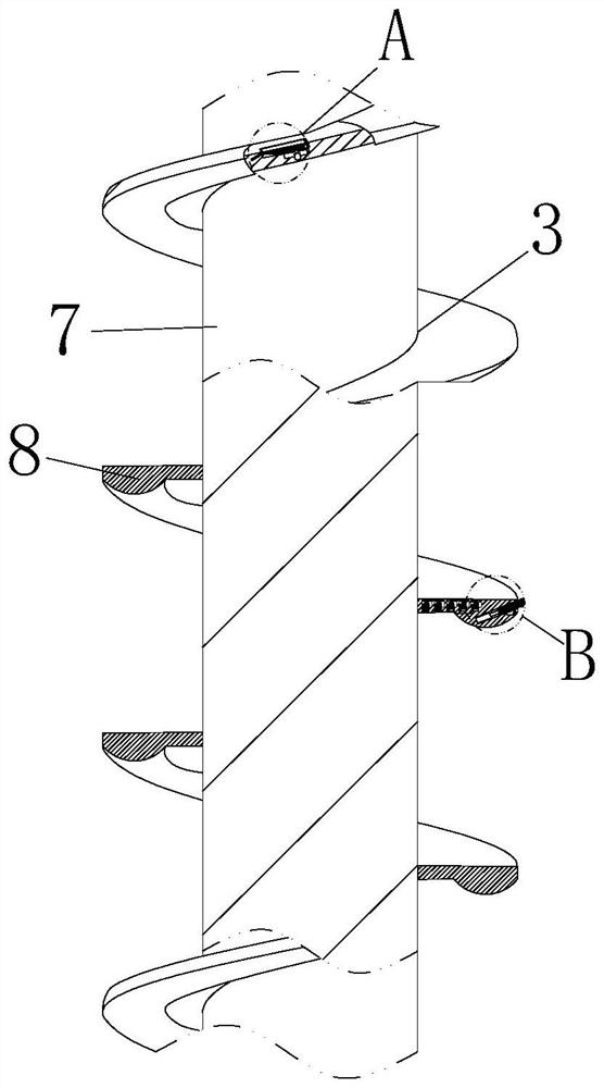
[0038] As an embodiment of the present invention, the sides of the rotating grooves are all provided with chute; the inside of the chute is slidably connected with a slider 13; between the slider 13 and the groove bottom of the corresponding chute The first spring is fixedly connected; the corrugated elastic sheet 14 is fixedly connected between the corresponding baffle plates 9 of the slider 13; during work, by setting the slider 13, when the baffle plate 9 rotates and leads to the corresponding rotation groove, the baffle plate 9 It will drive the corrugated elastic sheet 14 to stretch, and during the stretching process of the corrugated elastic sheet 14, the corrugated elastic sheet 14 will pull the slider 13, so that the slider 13 slides inside the corresponding chute, and stretches the first spring, and the derived corrugated The elastic sheet 14 can seal the notch of the rotating groove, so as to prevent the earth and stone or water on the surface of the spiral blade 8 fr...


PUM


Abstract

The invention belongs to the technical field of building construction, and specifically relates to a construction method for filling a wall foundation with deep backfill soil. The auger drilling machine used in the construction method includes a body, a rotating column and an auger bit; the top of the body is provided with a The movement arm; the end of the movement arm is rotatably connected with a rotation column; the bottom surface of the rotation column is fixedly connected with a hydraulic cylinder; the bottom surface of the hydraulic cylinder is fixedly connected with a connecting column; the bottom surface of the connecting column is fixedly connected with a screw Drill bit; the auger bit includes a core column and a helical blade; the surface of the helical blade is provided with uniformly arranged rotating grooves; the internal rotation of the rotating groove is connected with a baffle plate; the present invention effectively improves the carrying capacity of the auger bit The ability of soil and rock avoids a large amount of soil and rock falling when the auger bit is exported to the pile hole, which reduces the drilling efficiency and affects the introduction of the steel pipe pile into the pile hole in the later stage, so as to improve the pile hole drilling capacity of the auger drill.

Description

technical field [0001] The invention belongs to the technical field of building construction, and in particular relates to a construction method for filling a wall foundation with deep backfill soil. Background technique [0002] According to the formation and the soil rejection of the drill bit, it is divided into single-head single-screw, double-head single-screw, and double-head double-screw. The diameter of the drill hole is Ф400-1200mm. [0003] According to CN110924404A, a deep backfill soil filling wall foundation construction method, the deep backfill soil filling wall foundation construction method avoids pipeline deformation and filling wall cracking caused by backfill settlement. [0004] But in the prior art, after completing a drilling, it is necessary to export the auger bit. When the auger bit is exported, it can take out the earth and rocks, and then rotate or vibrate the auger bit outside the pile hole to make the earth and rock fall. Because the helical bl...

Claims


Application Information

Patent Timeline
Patent Type & Authority Patents(China)
IPC IPC(8): E02D5/38E02D27/12E21B3/00E21B17/22
CPCE02D5/38E02D27/12E21B3/00E21B17/22
Inventor 汪一新陈玲媚倪张江周凤中陶琼珍
Owner 温州城建集团股份有限公司
Why Eureka
Try Eureka