
Evaporation device of vehicle air conditioner and commercial locomotive

A technology for evaporating devices and vehicle air conditioners, which is applied to evaporators/condensers, refrigerators, vehicle components, etc., and can solve problems such as poor evaporation effect, poor evaporation effect at the top of the evaporator, and uneven heat transfer of the evaporator

Pending Publication Date: 2021-06-08
CHONGQING SANDIAN AUTOMOTIVE AIR CONDITIONING
View PDF4 Cites 1 Cited by
  • Summary
  • Abstract
  • Description
  • Claims
  • Application Information

AI Technical Summary

Problems solved by technology

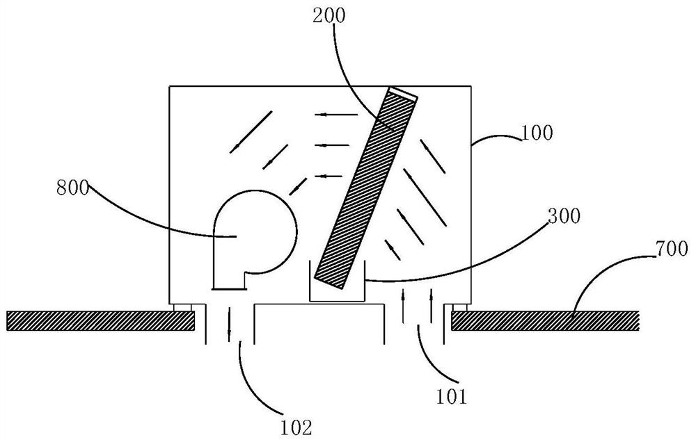
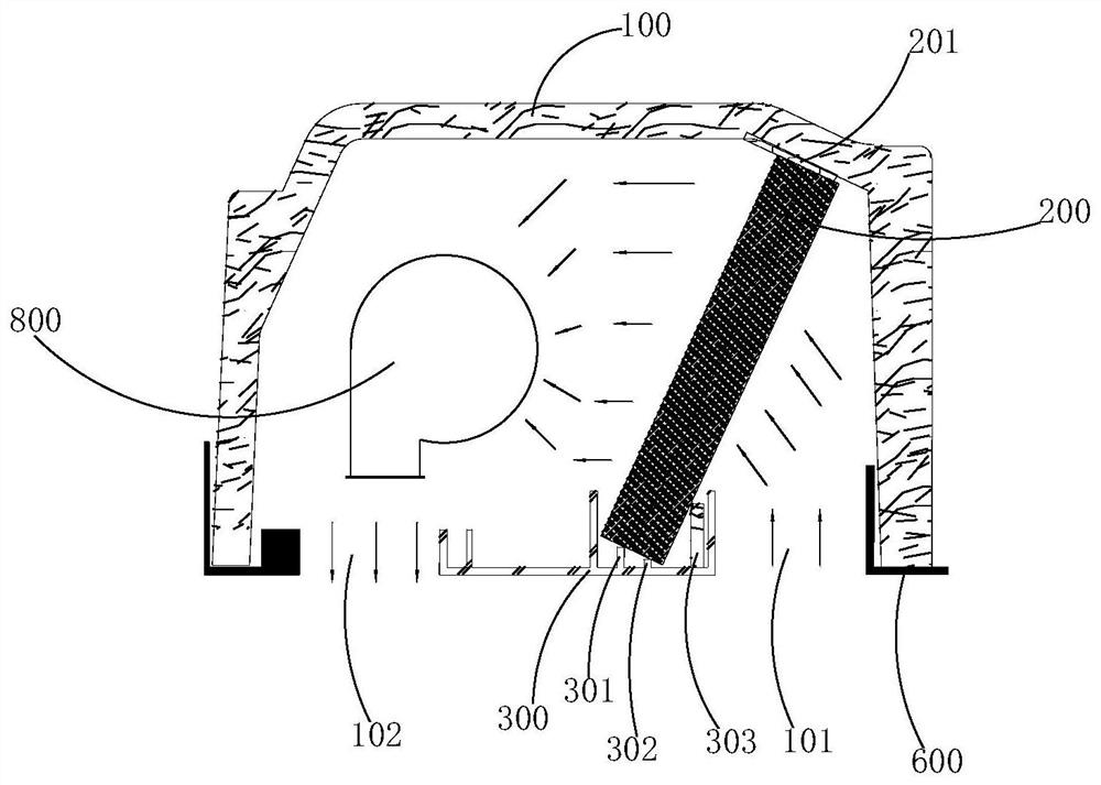
[0002] The evaporation system assembly of the overhead parking air conditioner is limited by the size of the cab skylight and the overall height of the overhead parking air conditioner. The size of the evaporation system assembly is usually relatively small. There are evaporation fans, evaporators, and air outlets inside the evaporation system assembly. part, the air return port part, including these four parts in a small space will lead to a very compact space arrangement. The conventional design method of the evaporator is vertical and vertical, and the overall size of the evaporator will be relatively small. The wind field of the evaporator is downward At this time, the wind field passed by the evaporator will be very uneven, resulting in uneven heat transfer of the evaporator and poor evaporation effect, which will reduce the cooling capacity of the entire parking air conditioning system and the use effect of the driver.
[0003] The conventional way of placing the evaporator in the evaporator assembly of the overhead parking air conditioner is to place it vertically. At the bottom part, the wind field at the top of the evaporator will be very bad, resulting in poor evaporation effect at the top of the evaporator and poor cooling effect
In addition, due to the narrow installation space, the windward and heat transfer area of ​​the evaporator is also relatively small, which also affects the cooling effect.

Method used


Image

  • Evaporation device of vehicle air conditioner and commercial locomotive
  • Evaporation device of vehicle air conditioner and commercial locomotive
  • Evaporation device of vehicle air conditioner and commercial locomotive

Examples


Embodiment Construction

[0042] In order to enable those skilled in the art to better understand the solutions of the present invention, the technical solutions in the embodiments of the present invention will be clearly and completely described below in conjunction with the drawings in the embodiments of the present invention.

[0043] In some processes described in the specification and claims of the present invention and the above-mentioned drawings, a plurality of operations appearing in a specific order are contained, but it should be clearly understood that these operations may not be performed in the order in which they appear herein Execution or parallel execution, the serial numbers of the operations, such as 101, 102, etc., are only used to distinguish different operations, and the serial numbers themselves do not represent any execution order. Additionally, these processes can include more or fewer operations, and these operations can be performed sequentially or in parallel. It should be n...


PUM


Abstract

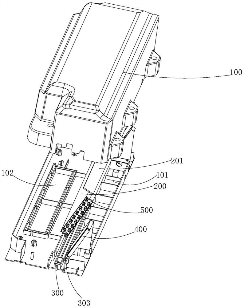
The invention discloses an evaporation device of a vehicle air conditioner. The evaporation device comprises a sealing shell, an evaporator is arranged in the sealing shell, the bottom of the evaporator is supported on the bottom wall of the sealing shell, and the top of the evaporator abuts against the top wall of the sealing shell; an air inlet is formed in one side of the bottom wall of the sealing shell, and an air outlet is formed in the other side of the bottom wall of the sealing shell; and the evaporator is obliquely arranged towards one side of the air inlet. According to the structural design of the evaporation device, on one hand, the windward and heat exchange area of the evaporator can be increased, and on the other hand, uniform heat exchange can be realized at the top and the bottom of the evaporator, so that the overall heat exchange effect is effectively improved. In addition, the invention further discloses a commercial locomotive.

Description

technical field [0001] The present application relates to the technical field of air conditioners, in particular to an evaporation device for vehicle air conditioners. Furthermore, the present application also relates to a commercial locomotive. Background technique [0002] The evaporation system assembly of the overhead parking air conditioner is limited by the size of the cab skylight and the overall height of the overhead parking air conditioner. The size of the evaporation system assembly is usually relatively small. There are evaporation fans, evaporators, and air outlets inside the evaporation system assembly. part, the air return port part, including these four parts in a small space will lead to a very compact space arrangement. The conventional design method of the evaporator is vertical and vertical, and the overall size of the evaporator will be relatively small. The wind field of the evaporator is downward At this time, the wind field passed by the evaporator w...

Claims


Application Information

Patent Timeline
Patent Type & Authority Applications(China)
IPC IPC(8): F25B39/02B60H1/00B60H1/32
CPCF25B39/02B60H1/00507B60H1/3227
Inventor 纪旭日李明洋王振宝陈超候庆林卢甲甲
Owner CHONGQING SANDIAN AUTOMOTIVE AIR CONDITIONING
Learn More