Cooling, vacuum sealing and insulating device suitable for semiconductor processing degumming process

A technology of vacuum sealing and insulating devices, which is applied in household refrigeration devices, cooling fluid circulation devices, semiconductor/solid-state device manufacturing, etc. It can solve problems such as insufficient cooling, risky insulation, and damage to component connections to achieve cooling and cooling effects Good, reduce welding, increase the effect of the loop

Active Publication Date: 2021-06-08
ADVANCED MATERIALS TECH & ENG INC
View PDF10 Cites 0 Cited by
  • Summary
  • Abstract
  • Description
  • Claims
  • Application Information

AI Technical Summary

Problems solved by technology

[0004] 1. In terms of cooling, the cooling is insufficient, the sealing is complicated, the process is complicated, and the cost is high
[0005] 2. In terms of vacuum sealing, the structure and process are complex and the cost is high
[0006] 3. In terms of insulation, insulation is risky, and the connection of components will be damaged and will be turned on

Method used


Image

  • Cooling, vacuum sealing and insulating device suitable for semiconductor processing degumming process
  • Cooling, vacuum sealing and insulating device suitable for semiconductor processing degumming process
  • Cooling, vacuum sealing and insulating device suitable for semiconductor processing degumming process

Examples


Embodiment 1

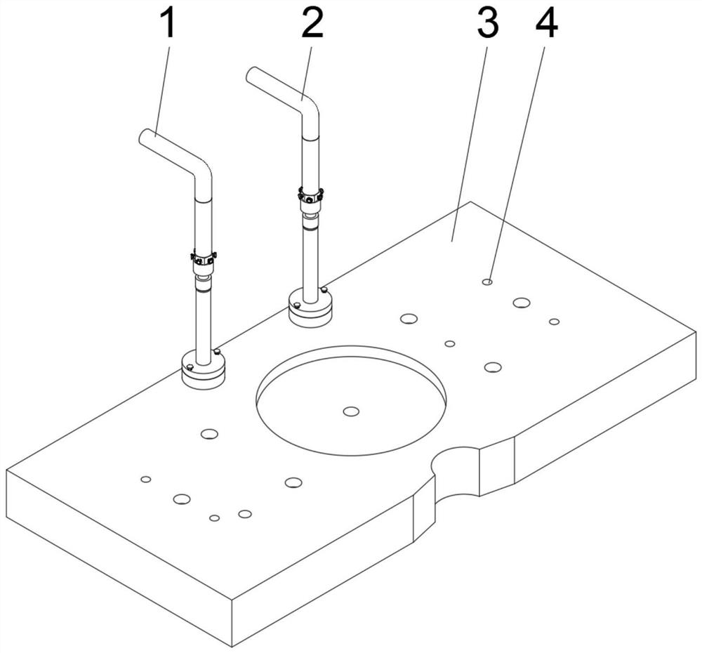
[0041] see figure 1 , an embodiment provided by the present invention: a cooling, vacuum sealing and insulating device suitable for semiconductor processing degumming process, including a first cooling mechanism 1, a second cooling mechanism 2, a cooling block main body 3 and a threaded fixing hole 4. The first cooling mechanism 1 and the second cooling mechanism 2 are screwed and fixedly installed on the upper end of one side of the cooling block main body 3, and the screw fixing installation holes 4 are evenly opened at both ends of the cooling block main body 3, and the first cooling mechanism 1 and the The structural specifications of the second cooling mechanism 2 are the same;

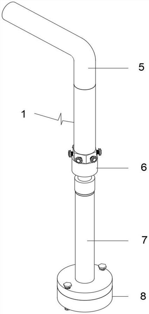
[0042] see figure 2 and Figure 7 , the first cooling mechanism 1 includes an insulating pipe 5, a first connecting sealing device 6, a connecting pipe 7 and a second connecting sealing device 8, and the connecting pipe 7 is fixedly installed between the first connecting sealing device 6 and t...

Embodiment 2

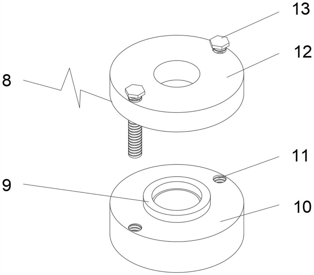
[0049] On the basis of Example 1, such as Figure 9-10 As shown, the upper end of the fastening threaded column 13 is fixedly equipped with a screw handle 28, the middle part of the screw handle 28 is a metal block, the outside of the metal block is wrapped with a rubber sleeve, and the inside of the sealing socket 16 is fixedly embedded with a non-slip seal ring. 29. The anti-skid sealing ring 29 is made of rubber.

[0050] When implementing this embodiment, the upper end of the fastening threaded post 13 is fixedly installed with a screw handle 28, and the middle part is a metal block, and the outside of the metal block is wrapped with a rubber sleeve, so as to facilitate the installation of the first step insulating flange 12. Screwing, if there is no basis, the first cooling mechanism 1, the second cooling mechanism 2 and the cooling block main body 3 can be quickly fixed and fast fixedly connected, and the inside of the sealing insertion groove 16 is fixedly embedded with...


PUM


Abstract

The invention discloses a cooling, vacuum sealing and insulating device suitable for a semiconductor processing degumming process. The device comprises a first cooling mechanism, a second cooling mechanism, a cooling block main body and threaded fixing mounting holes. The first cooling mechanism and the second cooling mechanism are fixedly mounted at the upper end of the middle part of one side of the cooling block main body in a threaded manner. The threaded fixing mounting holes are uniformly formed in the two ends of the cooling block main body, the first cooling mechanism comprises an insulating pipe, a first connecting and sealing device, a connecting pipe and a second connecting and sealing device, and the connecting pipe is fixedly mounted between the first connecting and sealing device and the second connecting and sealing device. In the using process, a cold water loop is added, and the cooling sectional area is increased; and welding is reduced, the cost is reduced, the manufacturing process is optimized, the service life is prolonged, assembly processing, assembling and maintenance are convenient, the cost is low, insulation is stable, all parts are effectively isolated, extra conduction is not formed, and damage to products by secondary discharge of charges is not caused.

Description

technical field [0001] The invention relates to the technical field of semiconductor processing, in particular to a cooling, vacuum sealing and insulating device suitable for the degumming process of semiconductor processing. Background technique [0002] According to Chinese Patent No. CN201521141516.4, this patent discloses a degumming device, including degumming equipment. The degumming equipment is provided with two degumming scrapers, and the two degumming scrapers can move relatively for clamping or loosening. Wait to remove the glue blade. The glue removing device of the utility model can greatly reduce the glue thread quantity of the film cutting blade and ensure the film cutting quality of the product. It can also save the glue removal step of the utility knife, and at the same time reduce the replacement frequency of the film cutting blade, and can even be used until the film cutting blade becomes blunt. The product quality and equipment utilization rate are grea...

Claims


Application Information

Patent Timeline
Patent Type & Authority Applications(China)
IPC IPC(8): F25D31/00F25D17/02B26D7/00H01L21/67
CPCF25D31/00F25D17/02B26D7/00H01L21/67011B26D2007/0012
Inventor 廖海涛
Owner ADVANCED MATERIALS TECH & ENG INC
Why Eureka
Try Eureka