Non-contact detection system and detection method for overhead lines

A non-contact detection system technology, applied in the field of pantograph-catenary detection, can solve the problems of inaccurate mechanical installation, increase the weight of the pantograph, increase the error, etc., achieve strong anti-interference ability, improve detection accuracy, reduce The effect of small vibration disturbances

Pending Publication Date: 2021-06-08
成都天佑路创轨道交通科技有限公司
View PDF9 Cites 1 Cited by
  • Summary
  • Abstract
  • Description
  • Claims
  • Application Information

AI Technical Summary

Problems solved by technology

[0004] At present, the geometric parameter detection of catenary is mainly contact detection, which is mainly carried out by installing corresponding photoelectric sensors and angular displacement sensors at specific positions on the pantograph. However, due to the inaccuracy of mechanical installation and the installed sensor Increase the weight of the pantograph and increase the detection error

Method used


Image

  • Non-contact detection system and detection method for overhead lines
  • Non-contact detection system and detection method for overhead lines
  • Non-contact detection system and detection method for overhead lines

Examples


Embodiment 1

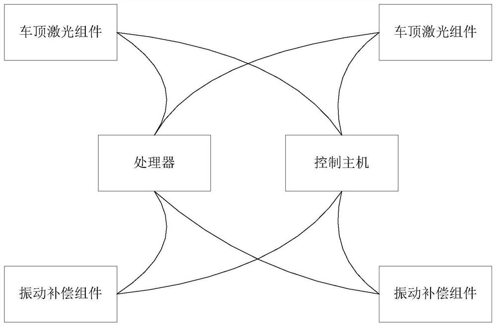
[0043] This embodiment provides a non-contact detection system for catenary, such as figure 1 shown, including:

[0044] The roof laser component is used to install on the roof, measure and obtain the roof detection data, and transmit the roof detection data to the processor. The roof detection data includes the height and lateral offset of the catenary relative to the laser component;

[0045] The vibration compensation component is used to install on the bottom of the car, measure and obtain the bottom compensation data, and transmit the bottom compensation data to the processor. The bottom compensation data includes the position deviation between the center of the car body and the center of the track and the height of the car body and the track Difference;

[0046] a processor for calculating the geometric parameters of the catenary according to the vehicle roof detection data and the vehicle bottom compensation data;

[0047] The control host is used to provide synchroni...

Embodiment 2

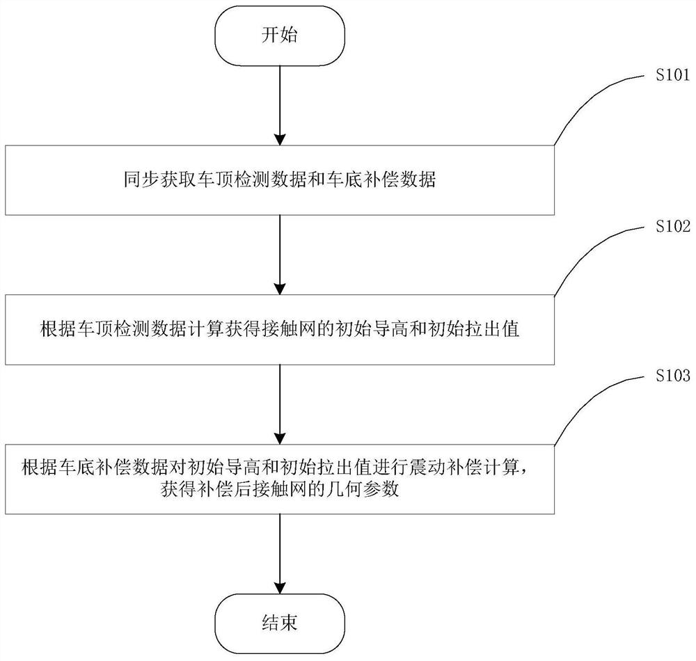
[0053] As an optimization of the above embodiments, this embodiment provides a non-contact detection method for catenary, such as image 3 shown, including the following steps:

[0054] S101. Obtain vehicle roof detection data and vehicle bottom compensation data synchronously. The control host can control the roof laser component and the vibration compensation component for synchronous data acquisition, and obtain the corresponding roof detection data and vehicle bottom compensation data. The reason why synchronous data is obtained is to eliminate compensation errors caused by data out-of-synchronization, so as to improve detection accuracy.

[0055] S102. Calculate and obtain the initial guide height and initial pull-out value of the catenary according to the detection data of the vehicle roof. When installing the roof laser component, the set position of the roof laser component is the reference position, and the height and lateral offset of the catenary relative to the l...


PUM


Abstract

The invention relates to the technical field of pantograph-catenary detection, in particular to a non-contact detection system and method for overhead lines. The system comprises a car roof laser assembly which is used for being installed on a car roof, obtaining car roof detection data through measurement and transmitting the car roof detection data to a processor, wherein the car roof detection data comprises the height and the transverse offset of a contact net relative to the laser assembly; a vibration compensation assembly which is used for being installed at the vehicle bottom, obtaining vehicle bottom compensation data through measurement and transmitting the vehicle bottom compensation data to the processor, wherein the vehicle bottom compensation data comprises the position deviation of the vehicle body center and the track center and the height difference of the vehicle body and the track; a processor used for calculating geometric parameters of the contact network according to the vehicle roof detection data and the vehicle bottom compensation data; and a control host used for providing a synchronizing signal and a power supply for the car roof laser assembly, the vibration compensation assembly and the processor. According to the invention, the geometric parameters of the overhead line system can be dynamically detected in a non-contact manner, vibration interference is eliminated through vibration compensation, and the detection accuracy is improved.

Description

technical field [0001] The invention relates to the technical field of pantograph-catenary detection, in particular to a non-contact detection system and detection method for a catenary. Background technique [0002] The pantograph-catenary system is an important part of the electrified railway power supply system, including the pantograph and the catenary. The electric locomotive obtains electric energy through the sliding contact between the pantograph slide plate and the catenary during operation. Due to the long-term sliding friction between the pantograph and the catenary, the geometric parameters of the catenary are likely to be affected. In order to ensure the safety of the electric locomotive, the geometric parameters of the catenary must be checked frequently to detect line faults in time and provide important references for operation and maintenance. [0003] The main content of the detection of the geometric parameters of the catenary is the guide height and pull-...

Claims


Application Information

Patent Timeline
Patent Type & Authority Applications(China)
IPC IPC(8): G01B11/02G01B11/24
CPCG01B11/02G01B11/24
Inventor 林建辉伍川辉林鹏飞邓韬何刘
Owner 成都天佑路创轨道交通科技有限公司
Why Eureka
Try Eureka