
Optical fiber parameter measuring device for correcting nonlinear tuning effect

A technology of nonlinear tuning and optical fiber parameters, which is applied in the direction of measuring devices, using optical devices to transmit sensing components, and reducing undesired effects, etc., can solve the requirements of measuring distance, computing efficiency, compensation effect limitation, and sampling rate. High, effective test distance and other issues, to achieve the effect of improving the correction effect, small data volume, and low cost

Active Publication Date: 2021-06-08
NANJING UNIV
View PDF5 Cites 9 Cited by
  • Summary
  • Abstract
  • Description
  • Claims
  • Application Information

AI Technical Summary

Problems solved by technology

The one-dimensional interpolation method proposed by J.Song et al. has a simple and easy-to-understand principle, but has high requirements on sampling rate, large amount of data processing, and low operation efficiency; the non-uniform fast Fourier transform proposed by Z.Ding et al. method, the data processing process is simple, but the effective test distance is short, and the compensation effect will drop sharply when the optical fiber to be tested is slightly longer; the zero-crossing resampling method based on the time scale factor proposed by J.Xing et al. Improvement, this method alleviates the impact of the length of the first delay fiber on the maximum measurement range, and reduces the requirements for the sampling rate. The disadvantage is that it is difficult to accurately obtain the zero-crossing point of the beat frequency signal of the auxiliary interferometer
Therefore, the current compensation methods are limited to varying degrees in terms of measurement distance, computing efficiency, and compensation effects.

Method used


Image

  • Optical fiber parameter measuring device for correcting nonlinear tuning effect
  • Optical fiber parameter measuring device for correcting nonlinear tuning effect
  • Optical fiber parameter measuring device for correcting nonlinear tuning effect

Examples


Embodiment Construction

[0032] In order to make the purpose, technical solution and advantages of the present application clearer, the present application will be further described in detail below in conjunction with the accompanying drawings and embodiments. It should be understood that the specific embodiments described here are only used to explain the present application, and are not intended to limit the present application.

[0033] Reference herein to an "embodiment" means that a particular feature, structure, or characteristic described in connection with the embodiment can be included in at least one embodiment of the present application. The occurrences of this phrase in various places in the specification are not necessarily all referring to the same embodiment, nor are separate or alternative embodiments mutually exclusive of other embodiments. It is understood explicitly and implicitly by those skilled in the art that the embodiments described herein can be combined with other embodiment...


PUM


Abstract

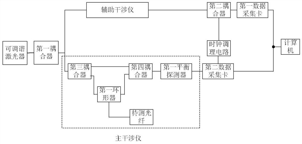
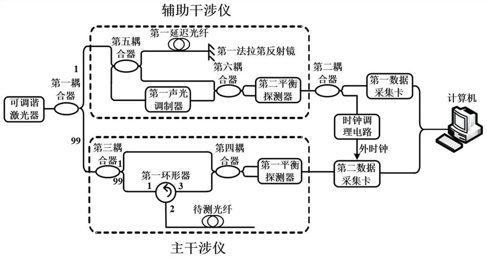
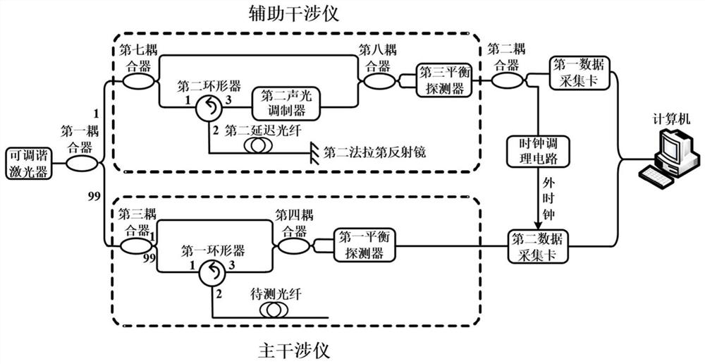
The invention discloses an optical fiber parameter measuring device for correcting a nonlinear tuning effect. The device is characterized in that firstly, an acoustic optical modulator (AOM) is connected into an auxiliary interferometer of an OFDR and is used for carrying out frequency shift on light waves and increasing the frequency of a beat frequency signal; then the beat frequency signal is converted into an electric signal by a balance detector, the electric signal is divided into two circuits by an electric coupler, one signal is acquired by a data acquisition card with a high sampling rate, and the other signal is used as an external clock for signal acquisition of a main interferometer; and finally, the signal of the main interferometer is corrected through the simple data processing and by taking the signal zero crossing point of the auxiliary interferometer as a reference. According to the device, the high-precision measurement data can be obtained with lower cost, the redundant data volume is reduced, and the correction accuracy of nonlinear frequency sweeping of a laser in the OFDR and the operation speed of data processing can be improved at the same time.

Description

technical field [0001] The invention relates to the technical field of distributed optical fiber sensing, in particular to an optical fiber parameter measurement device for correcting nonlinear tuning effects. Background technique [0002] Optical Frequency Domain Reflectometer (OFDR) is a fiber optic sensing technology based on the principle of optical heterodyne detection. It was first proposed in 1981 by W. Eickhoff et al. after learning from the frequency modulation continuous wave technology in the microwave field. Compared with the traditional optical time domain reflectometer, this technology has higher spatial resolution, sensing accuracy and sensitivity, and has important application value in the fields of safety monitoring of building structures, performance testing of communication devices and medical imaging. [0003] In a typical OFDR system, the linear sweep light emitted by the tunable laser is divided into two paths, one path is incident as a reference light ...

Claims


Application Information

Patent Timeline
IPC IPC(8): G01D5/353G01D3/028G01D3/06
CPCG01D5/35306G01D5/35329G01D5/35325G01D5/35361G01D5/35367G01D3/028G01D3/06Y02A90/10
Inventor 王峰夏益华孙莹陈强张旭苹张益昕
Owner NANJING UNIV
Learn More