Eureka AIR delivers breakthrough ideas for toughest innovation challenges, trusted by R&D personnel around the world.

Flotation column and liquid level regulation and control system and method thereof

A control system and flotation column technology, applied in flotation, solid separation, etc., can solve the problems of reducing the potential energy of ore pulp, frequent replacement of valve 8, and environmental pollution, so as to reduce equipment investment costs, improve production and operation conditions, and reduce environmental pollution. pollution effect

Pending Publication Date: 2021-06-11
CENT SOUTH UNIV +1
View PDF0 Cites 0 Cited by
  • Summary
  • Abstract
  • Description
  • Claims
  • Application Information

AI Technical Summary

Problems solved by technology

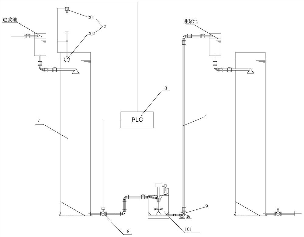
[0006] 1. The flow medium of valve 8 is ore pulp, which often passes through the flow parts of valve 8 at high speed. The ore particles (especially hard particles and coarse particles) in the slurry cause the flow parts of valve 8 to wear easily. 8 Frequent replacement affects the operation rate of the equipment
[0007] 2. The decompression control of valve 8 reduces the potential energy of the pulp. When the pulp is going to enter the next operation equipment with the same height configuration, the system needs to add additional lifting equipment such as stirring tank 101 + sand pump 9 to feed the pulp into the next operation. equipment, otherwise the lower operating equipment will reduce the configuration height, thus increasing the energy consumption of the system
[0008] 3. The height of the pulp discharge point is lower than the liquid level of the equipment, and it is open and exposed. When the follow-up operation equipment fails, it is easy to cause a pulp overflow accident, resulting in environmental pollution and the loss of useful metals

Method used


Image

  • Flotation column and liquid level regulation and control system and method thereof
  • Flotation column and liquid level regulation and control system and method thereof

Examples


Embodiment Construction

[0037] The following will clearly and completely describe the technical solutions in the embodiments of the present invention with reference to the accompanying drawings in the embodiments of the present invention. Obviously, the described embodiments are only some, not all, embodiments of the present invention. Based on the embodiments of the present invention, all other embodiments obtained by persons of ordinary skill in the art without creative efforts fall within the protection scope of the present invention.

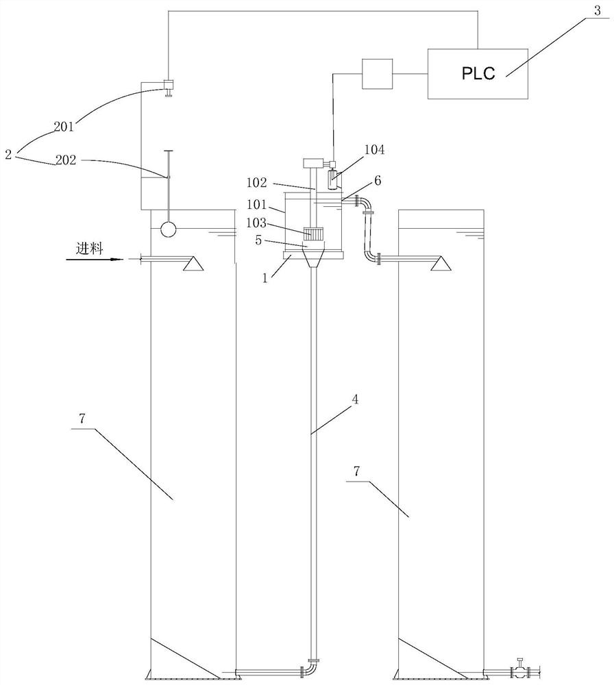
[0038] see figure 2 , a flotation column liquid level control system, including a lifting agitator 1, a liquid level detection device 2, a controller 3 and a slurry discharge pipe 4, the lifting agitator 1 includes a stirring tank body 101 and is arranged in the stirring tank body 101 vertical A stirring shaft 102 is arranged directly, and the bottom end of the stirring shaft 102 is provided with a lifting impeller 103, and the stirring tank body 101 is provided w...


PUM


Abstract

The invention discloses a flotation column and a liquid level regulation and control system and method thereof. The regulation and control method comprises the steps that a slurry discharging opening in the bottom of a column body is connected with a lifting stirrer through a slurry discharging pipe, and the lifting stirrer comprises a stirring tank body and a lifting impeller arranged in the stirring tank body; the lifting stirrer is started so that the lifting impeller rotates, blades of the lifting impeller rapidly empty surrounding ore pulp to form negative pressure, and the ore pulp enters the stirring tank body from the column body slurry discharging pipe and is discharged from the slurry discharging opening of the stirring tank body after being lifted by a set height; when a liquid level sensor on the column body senses that the liquid level in the column body is not at the set height, a signal is fed back to a controller; and the controller adjusts the rotating speed of the lifting impeller according to the received feedback signal, so that the slurry discharging speed of the slurry discharging pipe is controlled, and the liquid level in the column body is controlled at the set height. The ore pulp potential energy of the upstream column body is fully utilized, and the ore pulp can be lifted to a certain height through low energy consumption, so that the feeding requirement of the downstream same-level configuration column body is met.

Description

technical field [0001] The invention belongs to the technical field of mineral processing flotation, and in particular relates to a flotation column and its liquid level control system and method. Background technique [0002] Countercurrent flotation column (abbreviated as flotation column) is a kind of flotation equipment. By installing a bubble generator at the bottom of a columnar container, the pulp is fed from the upper part of the container, and the downstream pulp collides with the rising bubbles. The air bubbles thus capture and absorb the floating minerals (technically called "mineralization") and are discharged from the top of the vessel. Thereby the separation between minerals is achieved. [0003] The purpose of the flotation column is to separate the useful minerals from the useless minerals. Usually, the useful minerals are brought out from the upper part of the flotation column with the air bubbles, while the useless minerals are discharged from the bottom o...

Claims


Application Information

Patent Timeline
Patent Type & Authority Applications(China)
IPC IPC(8): B03D1/14
CPCB03D1/14
Inventor 马驰宇孙伟胡岳华马士强
Owner CENT SOUTH UNIV
Why Eureka
Eureka Blog
Learn More