
Movable soil vapor extraction treatment device

A gas-phase extraction and processing device technology, which is applied in the field of mobile soil gas-phase extraction and processing devices, can solve the problems of inconvenient transportation of gas-phase extraction devices, and achieve the effect of improving convenience and device performance

Inactive Publication Date: 2021-06-11
潍坊方嘉环境科技有限公司 +1
View PDF0 Cites 0 Cited by
  • Summary
  • Abstract
  • Description
  • Claims
  • Application Information

AI Technical Summary

Problems solved by technology

[0004] The purpose of the present invention is to provide a mobile soil gas phase extraction treatment device, which solves the problem of inconvenient transfer of gas phase extraction devices in the prior art

Method used


Image

  • Movable soil vapor extraction treatment device
  • Movable soil vapor extraction treatment device
  • Movable soil vapor extraction treatment device

Examples


Embodiment 1

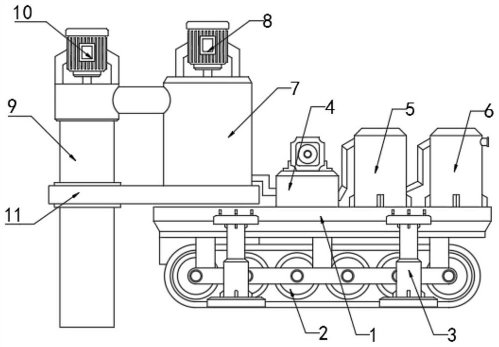
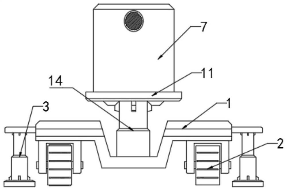
[0028] refer to Figure 1-6 , the present embodiment provides a mobile soil gas phase extraction treatment device, which includes: a car body 1, crawler belts 2 are provided on both sides of the car body 1, and the crawler belts 2 are controlled by the control system of the car body 1, and at the same time , the top of the car body 1 is fixedly connected with an air extraction system 4, a gas-liquid separation system 5, and an exhaust gas treatment system 6 in sequence from left to right, and between the air extraction system 4 and the gas-liquid separation system 5, the gas-liquid separation system 5 communicate with each other with the tail gas treatment system 6;

[0029] The air extraction system 4, the gas-liquid separation system 5 and the exhaust gas treatment system 6 adopt the existing technology, and the front end of the car body 1 is fixedly connected with a hydraulic cylinder 14, so that the bottom end of the hydraulic cylinder 14 is lower than the level of the car...

Embodiment 2

[0032] The only difference between this embodiment and Embodiment 1 is that the bottom end of the processing cylinder 7 is fixedly connected with an anti-seepage membrane mechanism to ensure that the gas in the air extraction system 4 will not flow back.

Embodiment 3

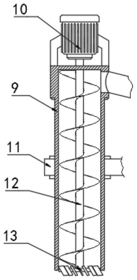
[0034] The only difference between this embodiment and Embodiment 1 is that, as Figure 1-3 As shown, the output end of the hydraulic cylinder 14 is fixedly connected to the connecting plate 11, and the top of the connecting plate 11 is fixedly connected to the processing cylinder 7. The lifting cylinder 9 and the processing cylinder 7 are transported synchronously to ensure a stable connection between the two, and at the same time ensure that the maximum downward transmission distance of the hydraulic cylinder 14 can reach the joint between the connecting plate 11 and the vehicle body 1 .


PUM


Abstract

The invention discloses a movable soil gas phase extraction treatment device. The device comprises a gas extraction system, a gas-liquid separation system and a tail gas treatment system, every two adjacent gas extraction system, gas-liquid separation system and tail gas treatment system communicate with each other, a hydraulic cylinder is fixedly connected to the front end of a vehicle body, the output end of the hydraulic cylinder is in transmission connection with a treatment cylinder and a lifting cylinder, the top ends of the treatment cylinder and the lifting cylinder are communicated through a connecting pipe, and a first screw rod and a second screw rod are rotationally connected to the interiors of the treatment cylinder and the lifting cylinder respectively. According to the device, the two screw rods in the lifting cylinder and the treatment cylinder are matched with each other, so that external soil is conveyed into the treatment cylinder to be subjected to vapor extraction treatment; and the two screw rods in the lifting cylinder and the treatment cylinder are reversely matched, the soil in the treatment cylinder is backfilled, recovery of an extraction area is completed, after the device completes one-time extraction, subsequent gas phase extraction operation in different areas can be carried out, and the convenience of the device is improved.

Description

technical field [0001] The invention relates to the technical field of soil gas phase extraction, in particular to a mobile soil gas phase extraction treatment device. Background technique [0002] Soil vapor phase extraction is a method of in-situ remediation of soil volatile organic pollution. It is used to deal with the pollution of the formation medium in the vadose zone. Through a special underground extraction system, the pressure generated by vacuuming or injecting air is used. Force the gas in the soil in the unsaturated zone to flow, so as to remove the volatile and semi-volatile organic pollutants and achieve the purpose of cleaning the soil. [0003] When performing gas-phase extraction of soil, it is necessary to build gas-phase extraction equipment in the corresponding area. When changing the site, all equipment needs to be transferred. The operation is very inconvenient, and the amount of engineering is large, which increases the cost of gas-phase extraction. ...

Claims


Application Information

Patent Timeline
IPC IPC(8): B09C1/00
CPCB09C1/00B09C2101/00
Inventor 郎洁李冰陈新陈仁涛
Owner 潍坊方嘉环境科技有限公司
Learn More