Optical lens high-precision polishing machine and its power transmission device

A technology of power transmission device and optical lens, which is applied in the direction of grinding drive device, grinding device, optical surface grinder, etc. It is convenient for production, processing and replacement, low precision requirements for assembly, and the effect of easy reclaiming and discharging

Active Publication Date: 2022-04-15
湖南新格兰德机械制造有限公司
View PDF7 Cites 0 Cited by
  • Summary
  • Abstract
  • Description
  • Claims
  • Application Information

AI Technical Summary

Problems solved by technology

[0005] 1. The traditional reverse rotation of the upper and lower grinding discs requires two motors to be driven separately, and the cost is high
[0006] 2. The upper grinding device and the main shaft in the traditional polishing processing equipment are always connected, and the upper grinding device and the lower grinding device cannot be separated, resulting in difficulties in feeding and retrieving materials, which is not conducive to production and processing
[0007] 3. The traditional large ring gear device is lifted and lowered through thread fit, which takes a long time for lifting and lowers, and requires high assembly accuracy
[0008] 4. During grinding, the workpiece performs a synthetic motion of rotation and revolution, and the conventional spraying method of grinding fluid cannot fully spray on the workpiece, resulting in poor polishing quality
[0009] 5. During the grinding process, due to the irregular surface of the workpiece, the grinding disc vibrates. If the grinding disc is completely fixed, the impact generated by the vibration will affect the grinding disc. If it is used for a long time, it is easy to damage the grinding disc

Method used


Image

  • Optical lens high-precision polishing machine and its power transmission device
  • Optical lens high-precision polishing machine and its power transmission device
  • Optical lens high-precision polishing machine and its power transmission device

Examples


Embodiment Construction

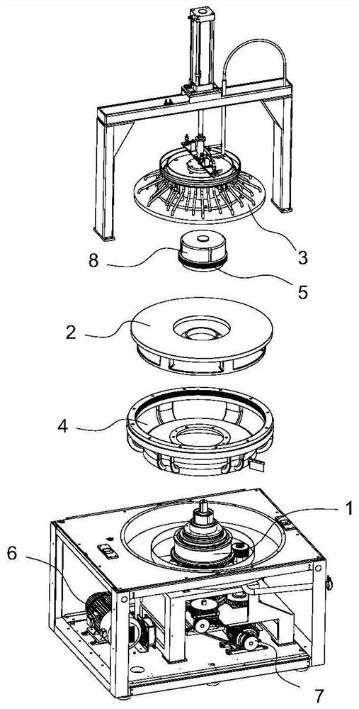
[0037] Such as figure 1As shown, a high-precision polishing machine for optical lenses, the processing equipment includes a frame and a power transmission device 1 installed on the frame, a lower grinding device 2, an upper grinding device 3, an upper grinding clutch device 8, a large ring gear device 4, A pinion gear arrangement 5 , a first motor 6 and a second motor 7 . The power transmission device 1 is arranged below the frame, and the upper grinding clutch device 8, the small ring gear device 5, the lower grinding device 2 and the large ring gear device 4 are installed on the power transmission device 1 sequentially from top to bottom. The upper grinding device 3 is vertically lifted and arranged on the top of the frame, and the upper grinding device 3 is positioned directly above the lower grinding device 2 . The bottom of the upper grinding device 3 cooperates with the upper grinding clutch device 8, and the upper grinding clutch device 8 controls the upper grinding de...


PUM


Abstract

The invention relates to the technical field of optical lens processing, in particular to a high-precision optical lens polishing machine and its power transmission device, including a main shaft assembly, a first motor transmission shaft assembly, a second motor transmission shaft assembly and a clutch assembly; the main shaft assembly includes a main shaft, a second A hollow shaft, a second hollow shaft, a fixed shaft seat, an upper grinding disc driven gear, a small ring gear driven gear, a lower grinding driven gear and a large ring gear driven gear; this patent fixes the upper grinding disc driven gear driving the upper grinding disc on the On the main shaft, the lower grinding driven gear that drives the lower grinding disc is fixed on the second hollow shaft, and the upper grinding disc driven gear and the lower grinding driven gear are assembled and connected by the first motor transmission shaft, so that the upper grinding disc driven gear and the lower grinding disc The passive gear rotates in reverse under the action of the same motor, which is beneficial to reduce costs.

Description

technical field [0001] The invention relates to the technical field of optical lens processing, in particular to a power transmission device and processing equipment of a high-precision optical lens polishing machine. Background technique [0002] Polishing machines, also known as grinders, are often used for mechanical grinding, polishing and waxing. Its working principle is: the motor drives the sponge or wool polishing disc installed on the polishing machine to rotate at high speed. Due to the joint action of the polishing disc and the polishing agent and friction with the surface to be polished, it can achieve the effect of removing paint surface pollution, oxide layer and shallow marks. Purpose. The rotational speed of the polishing disc is generally 1500-3000 r / min, mostly continuously variable. [0003] Existing polishing machines, such as the Chinese utility model patent (publication number: CN205033069U, publication date: 20160217) disclose a double-sided grinding...

Claims


Application Information

Patent Timeline
Patent Type & Authority Patents(China)
IPC IPC(8): B24B13/00B24B13/01B24B37/11B24B37/34B24B47/12B24B41/04B24B41/00B24B57/02B24B47/14
CPCB24B13/00B24B13/01B24B37/11B24B37/34B24B47/12B24B41/04B24B41/007B24B57/02B24B47/14
Inventor 王毛王成高唐晚雄
Owner 湖南新格兰德机械制造有限公司
Why Eureka
Try Eureka