Heat preservation partition plate connecting accessory and construction method thereof

A technology for connecting accessories and partitions, which is applied in the direction of thermal insulation, building components, walls, etc., and can solve the problem of low connection strength between thermal insulation partitions and steel beams, connection tolerances between thermal insulation partitions and steel beams, and reduced overall building stability. problems, to achieve the effect of improving convenience, reducing construction costs, and simple structure

Inactive Publication Date: 2021-06-11
GUANGDONG FIFTHS CONSTRUCTIONAL ENG CO LTD
View PDF6 Cites 2 Cited by
  • Summary
  • Abstract
  • Description
  • Claims
  • Application Information

AI Technical Summary

Problems solved by technology

However, there are processing errors in the size of the prefabricated insulation partitions in the factory, and there are assembly errors in the steel beams assembled at the construction site, so that there are connection tolerances between the insulation partitions and the steel beams
[0004] In view of the above-mentioned related technologies, the inventor believes that there are the following defects: when using welding to connect the thermal insulation partition and the steel beam, the weld between the thermal insulation partition and the steel beam is too large, which is not conducive to construction At the same time, the connection strength between the thermal insulation partition and the steel beam is low, which reduces the overall stability of the building

Method used


Image

  • Heat preservation partition plate connecting accessory and construction method thereof
  • Heat preservation partition plate connecting accessory and construction method thereof
  • Heat preservation partition plate connecting accessory and construction method thereof

Examples


Embodiment 1

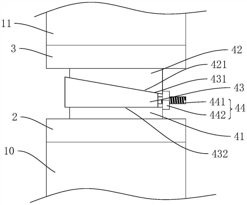
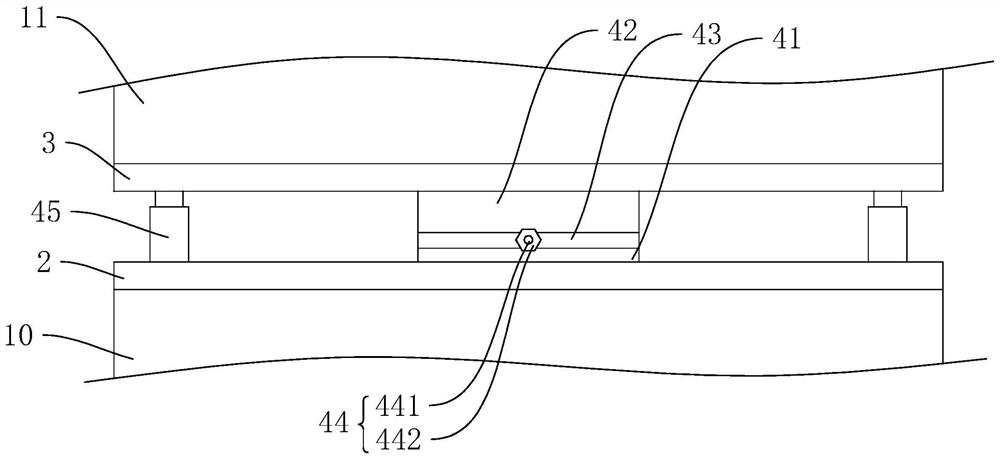
[0043] refer to figure 1 and figure 2 , the connecting accessories include a first connecting plate 2 and a second connecting plate 3, the first connecting plate 2 and the second connecting plate 3 are parallel to each other, a lifting device is arranged between the first connecting plate 2 and the second connecting plate 3, the lifting device It is used to drive the first connecting plate 2 and the second connecting plate 3 to approach or move away from each other.

[0044] In normal state, the first connecting plate 2 and the second connecting plate 3 are close to each other. After placing the connecting fittings in the gap between the thermal insulation partition 10 and the shaped steel beam 11, the lifting device is driven to make the first connecting plate 2 and the second connecting plate 3 are separated from each other, so that the first connecting plate 2 is contacted with the insulation partition plate 10, and the second connecting plate 3 is contacted with the shap...

Embodiment 2

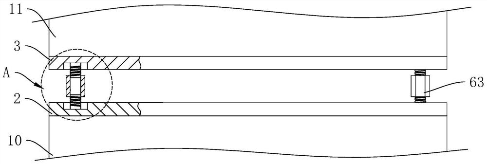
[0053] refer to image 3 and Figure 4 , The difference between this embodiment and Embodiment 1 lies in the structure of the lifting device. In this embodiment, the lifting device includes a first support rod 61 , a second support rod 62 and a connecting sleeve 63 . Wherein, the side facing each other of the first connecting plate 2 and the second connecting plate 3 is provided with a groove 64, and the two grooves 64 are arranged symmetrically, and the first supporting rod 61 and the second supporting rod 62 are installed in the two grooves 64 respectively. , the first support rod 61 and the second support rod 62 are arranged coaxially, and the connecting sleeve 63 is sleeved on the outside of the first support rod 61 and the second support rod 62 .

[0054] Wherein, the connecting sleeve 63 is provided with two sections of threaded sections 631 with opposite helical directions, and the inner wall of the connecting sleeve 63 is threadedly connected with the outer walls of ...

Embodiment 3

[0059] refer to Figure 6 and Figure 7 , The difference between this embodiment and Embodiment 1 lies in the structure of the lifting device. In this embodiment, the elevating device includes two parallel first connecting rods 71, two parallel second connecting rods 72 and a driving member 73, one end of the first connecting rod 71 and the first connecting plate 2 facing the second connecting plate 3 One side is hinged, and one end of the second connecting rod 72 is hinged with the second connecting plate 3 facing the side of the first connecting plate 2, the first connecting rod 71 and the second connecting rod 72 are arranged crosswise, the first connecting rod 71 and the second The middle part of connecting rod 72 is hinged.

[0060] Wherein, the side facing each other of the first connecting plate 2 and the second connecting plate 3 is provided with a sliding groove 74. Block 75, the end of the first connecting rod 71 away from the first connecting plate 2 is hinged wi...


PUM


Abstract

The invention relates to a heat preservation partition plate connecting accessory, and belongs to the technical field of fabricated buildings. The heat preservation partition plate connecting accessory comprises a first connecting plate and a second connecting plate which are arranged in parallel, wherein a lifting device is arranged between the first connecting plate and the second connecting plate, the lifting device is used for driving the first connecting plate and the second connecting plate to be close to each other or away from each other, the two sides, away from each other, of the first connecting plate and the second connecting plate are used for being fixedly connected with a heat preservation partition plate and a section steel beam correspondingly, and a joint mixture is arranged between the first connecting plate and the second connecting plate. According to the scheme, a gap between the heat preservation partition plate and the section steel beam is effectively filled, so that the connection between the heat preservation partition plate and the section steel beam is firmer, then the connection strength between the heat preservation partition plate and the section steel beam is enhanced, and the installation stability of the heat preservation partition plate is effectively improved.

Description

technical field [0001] The present application relates to the field of prefabricated buildings, in particular to a thermal insulation partition connection fitting and a construction method thereof. Background technique [0002] Prefabricated building refers to the transfer of a large number of on-site operations in the traditional construction method to the factory, where the building components and accessories (such as floors, wall panels, stairs, balconies, etc.) are processed and manufactured in the factory, and transported to the construction site. Reliable connections are assembled and installed on site. [0003] At present, the main connection methods between the thermal insulation partition and the building steel beam are welding, bolt connection or integral connection of post-cast concrete. However, there are processing errors in the size of the prefabricated insulation partitions in the factory, and assembly errors in the steel beams assembled on the construction s...

Claims


Application Information

Patent Timeline
Patent Type & Authority Applications(China)
IPC IPC(8): E04B2/74E04B2/82E04B1/80
CPCE04B2/74E04B2/82E04B1/80
Inventor 朱新魁黄燕平童林锋
Owner GUANGDONG FIFTHS CONSTRUCTIONAL ENG CO LTD
Why Eureka
Try Eureka