Environment-friendly plastic floor

A kind of plastic floor, environment-friendly technology, applied in the field of plastic floor, can solve the problems of affecting the flatness of the floor, damaging electronic components, wasting time, etc., to achieve the effect of enhancing structural strength, improving flame retardancy, and expanding the scope of use

Pending Publication Date: 2021-06-11
聂盼
View PDF0 Cites 0 Cited by
  • Summary
  • Abstract
  • Description
  • Claims
  • Application Information

AI Technical Summary

Problems solved by technology

[0003] In terms of form, it can be divided into two types: coil floor and sheet floor, especially sheet floor, which also has disadvantages in the process of use. The plastic floor has high requirements on the flatness of the construction site, and the surface of the construction site needs to be ventilated before laying. Cleaning up wastes time and wastes manpower and material costs, and the protrusions on the surface of the construction site directly affect the flatness of the floor, which damages the floor and weakens the competitiveness of the plastic floor in the market; the flame retardancy of the plastic floor is low, It is easy to burn and cause fire, and produces toxic gas after burning, which pollutes the environment and affects people's health; when people walk, shoes rub against the plastic floor to generate static electricity, and the static electricity generated by friction between shoes and the floor can not only damage electronic components and reduce the safety of electronic equipment The service life, and the charged ions will absorb the dust in the air and affect the indoor environmental sanitation, the floor needs to be cleaned and maintained regularly

Method used


Image

  • Environment-friendly plastic floor
  • Environment-friendly plastic floor
  • Environment-friendly plastic floor

Examples


Embodiment approach

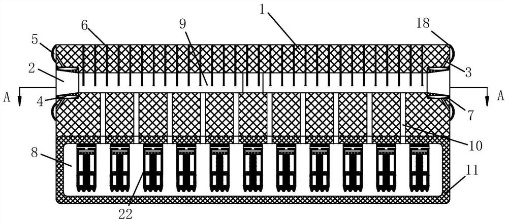
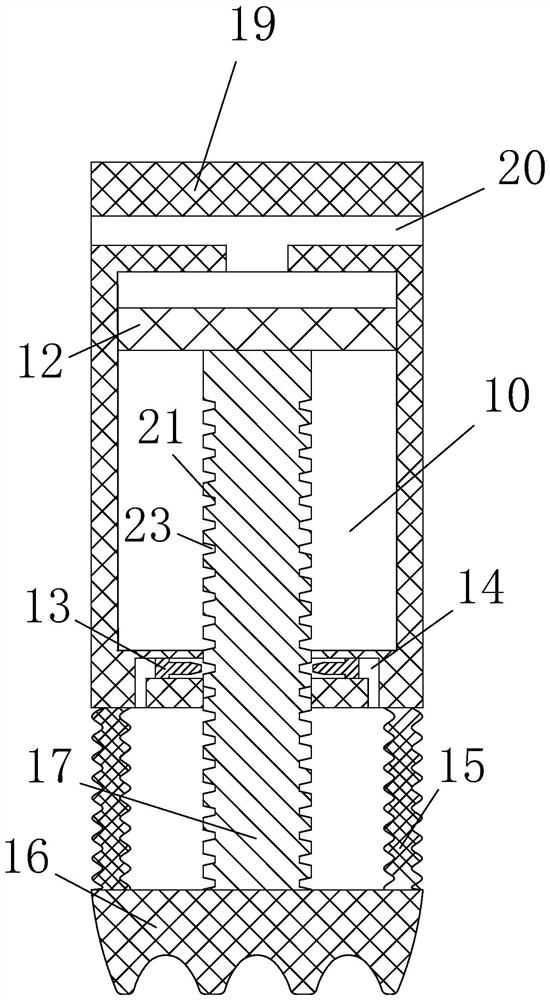
[0023] As an embodiment of the present invention, the support unit 19 includes a fixed rod 22, a support rod 17, a support pad 16 and an elastic film 15; the upper end of the fixed rod 22 is fixedly connected to the top inner wall of the rubber layer 11, and the fixed rod 22 A water pressure chamber is opened inside; a blocking plate 12 is sealed and slidably connected in the water pressure chamber; the upper end of the support rod 17 is fixedly connected to the lower surface of the blocking plate 12, and the lower end of the support rod 17 passes through the fixing rod 22 through a perforation and is placed on the The lower side of the fixed rod 22 is fixedly connected to the upper surface of the support pad 16, and the support rod 17 is slidably connected to the fixed rod 22; the lower surface of the fixed rod 22 is fixedly connected to the upper surface of the support pad 16 with an elastic film 15; the elastic film 15 has a ring design , and the elastic membrane 15 wraps th...


PUM


Abstract

The invention belongs to the technical field of plastic floors, and particularly relates to an environment-friendly plastic floor. The environment-friendly plastic floor comprises a floor body, connecting clamping grooves and supporting units; cross-shaped first water inlet grooves are formed in the plate body; the first water inlet grooves penetrate through the plate body and are provided with the connecting clamping grooves in one-to-one correspondence with the first water inlet grooves in the side face of the plate body; each supporting unit comprises a fixing rod, a supporting rod, a supporting pad and an elastic film; the upper end of each fixing rod is fixedly connected to the inner wall of the top of a rubber layer, and a water pressure cavity is formed in each fixing rod; a blocking plate is connected into each water pressure cavity in a sealed and sliding mode; the bottom of the plate body is fixedly connected with the rubber layer; and a water storage cavity is formed in the rubber layer. The flame retardant performance and the sound insulation effect of the plastic floor can be effectively improved, the use requirement of the plastic floor for the flatness of a construction site can be effectively lowered, therefore the market competitiveness of the floor is improved, the splicing mode of floors is optimized, and the overall structural strength of the floor is improved.

Description

technical field [0001] The invention belongs to the technical field of plastic floors, in particular to an environment-friendly plastic floor. Background technique [0002] With the improvement of people's awareness of environmental protection, the demand for environmentally friendly decorative materials is increasing. Plastic floor decorative materials are widely used in factories, hospitals, companies, shopping malls, airports and other places due to their excellent performance and easy processing characteristics; Plastic floor is another name for PVC floor. The main component is polyvinyl chloride material. PVC floor can be made into two types, one is homogeneous and transparent, that is, the pattern material from bottom to surface is the same; There is also a composite type, that is, the top layer is a pure PVC transparent layer, and a printing layer and a foaming layer are added below. [0003] In terms of form, it can be divided into two types: coil floor and sheet fl...

Claims


Application Information

Patent Timeline
Patent Type & Authority Applications(China)
IPC IPC(8): E04F15/02E04F15/024E04F15/10E04F15/18E04F15/20H05F3/00
CPCE04F15/02E04F15/02005E04F15/02016E04F15/02447E04F15/02464E04F15/10E04F15/181E04F15/206E04F2290/041E04F2290/045H05F3/00
Inventor 聂盼黄冬冬
Owner 聂盼
Why Eureka
Try Eureka