
Large-angle liquid crystal optical phased array scanning assembly

A liquid crystal optics and phased array technology, applied in optics, nonlinear optics, instruments, etc., can solve the problems of narrow beam scanning range, high cost, large beam insertion loss, etc., and achieve the effect of solving the narrow field of view.

Active Publication Date: 2021-06-11
UNIV OF ELECTRONIC SCI & TECH OF CHINA
View PDF17 Cites 1 Cited by
  • Summary
  • Abstract
  • Description
  • Claims
  • Application Information

AI Technical Summary

Problems solved by technology

At present, the control methods of laser scanning at home and abroad are roughly divided into two types: mechanical and non-mechanical. Mechanical deflection relies on mechanical devices to change the direction of the optical axis to achieve beam deflection. Its response is slow, there is mechanical inertia during scanning, and the device is bulky and expensive. Disadvantages such as high cost; non-mechanical beam deflection technology With the deepening of research and the maturity of manufacturing technology, liquid crystal optical phased array (LCOPA) technology has become a research hotspot. LCOPA has no inertia, high scanning accuracy and low SWaP (size, weight and power consumption) and other advantages, it is an important research direction in beam deflection
[0003] Liquid crystal optical phased array technology overcomes many shortcomings of mechanical deflection technology, but liquid crystal optical phased array technology also faces the problem of narrow beam scanning range (about ±3 °), mainly affected by the array size of the liquid crystal cell, the depth of phase modulation and the current process technology
At present, the large-angle scanning method adopts cascading technology. The cascading of devices brings high cost consumption, and the large number of cascading layers of light beams leads to large insertion loss.

Method used


Image

  • Large-angle liquid crystal optical phased array scanning assembly
  • Large-angle liquid crystal optical phased array scanning assembly
  • Large-angle liquid crystal optical phased array scanning assembly

Examples


Embodiment Construction

[0019] The technical solution of the present invention will be further described below in conjunction with the accompanying drawings.

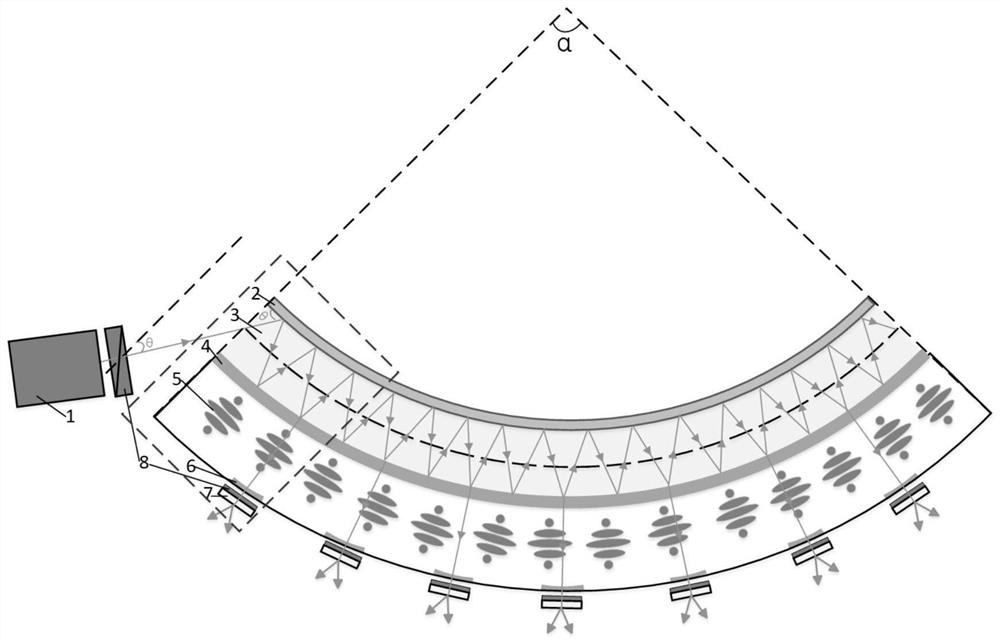
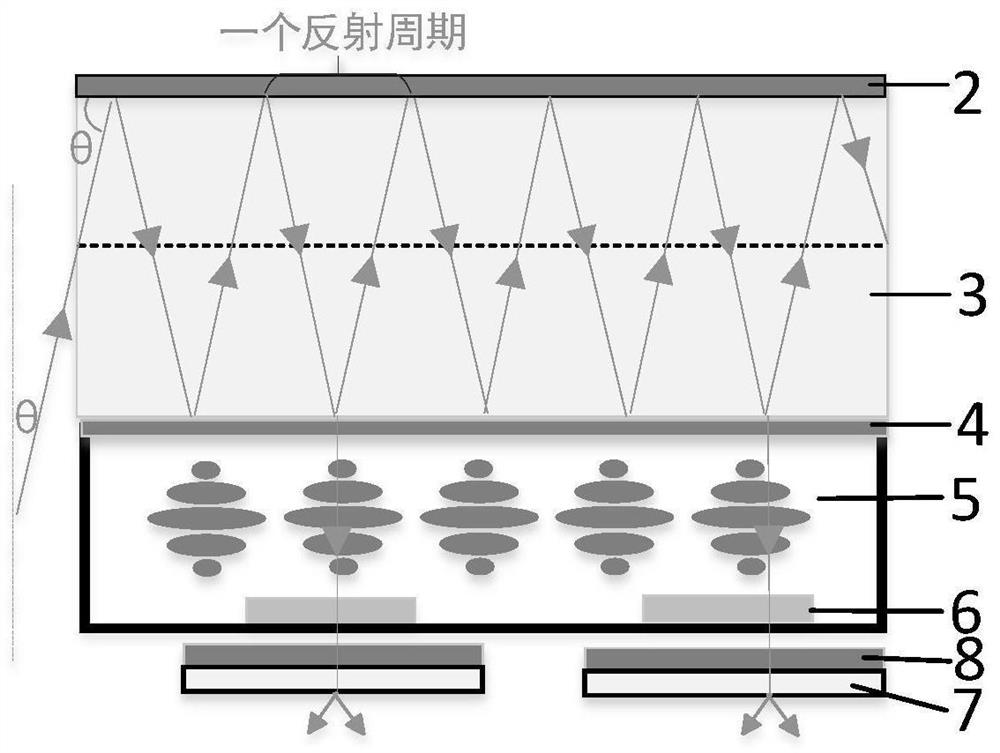
[0020] Such as figure 1 As shown, a large-angle liquid crystal optical phased array scanning assembly of the present invention includes a laser 1, a quarter wave plate, an optical waveguide 3, a cholesteric liquid crystal device 5 and a liquid crystal optical phased array 7; the laser 1 emits The laser is coupled into the optical waveguide 3 after passing through a quarter wave plate, and propagates along the optical waveguide; the optical waveguide 3 is in an arc-shaped structure, and the inner side of the optical waveguide 3 is provided with a metal reflective layer 2, and the outer side is provided with an ITO film layer 4 The outside of the ITO film layer 4 is provided with a plurality of cholesteric liquid crystal devices 5, and the outside of the cholesteric liquid crystal device 5 is successively provided with an ITO electrode 6, a quar...


PUM


Abstract

The invention discloses a large-angle liquid crystal optical phased array scanning assembly which comprises a laser, a quarter-wave plate, an optical waveguide, a cholesteric liquid crystal device and a liquid crystal optical phased array. Laser emitted by the laser passes through the quarter-wave plate, then is coupled into the optical waveguide and is propagated along the optical waveguide. The optical waveguide is of an arc-shaped structure, a metal reflecting layer is arranged on the inner side of the optical waveguide, and an ITO film layer is arranged on the outer side of the optical waveguide. A plurality of cholesteric liquid crystal devices are arranged on the outer side of the ITO film layer, and an ITO electrode, a quarter-wave plate and a liquid crystal optical phased array are sequentially arranged on the outer side of each cholesteric liquid crystal device; the cholesteric liquid crystal device is used as a selective switch for laser transmission or reflection. According to the invention, through selection of the cholesteric liquid crystal unit device, laser in the waveguide is reflected or transmitted to the liquid crystal optical phased array, so that scanning control is realized; a plurality of cholesteric liquid crystal unit devices and a plurality of liquid crystal optical phased arrays are adopted, so that large-angle scanning can be realized.

Description

technical field [0001] The invention belongs to the field of liquid crystal optical phased array technology and liquid crystal optoelectronic device technology, and particularly relates to a large-angle liquid crystal optical phased array scanning component. Background technique [0002] Beam deflection scanning technology is widely used in laser communication, target tracking and other fields. At present, the control methods of laser scanning at home and abroad are roughly divided into two types: mechanical and non-mechanical. Mechanical deflection relies on mechanical devices to change the direction of the optical axis to achieve beam deflection. Its response is slow, there is mechanical inertia during scanning, and the device is bulky and expensive. Disadvantages such as high cost; non-mechanical beam deflection technology With the deepening of research and the maturity of manufacturing technology, liquid crystal optical phased array (LCOPA) technology has become a resear...

Claims


Application Information

Patent Timeline
IPC IPC(8): G02F1/137G02F1/1343G02F1/13363G02F1/29
CPCG02F1/13718G02F1/1343G02F1/13363G02F1/292
Inventor 汪相如梁知清贺晓娴
Owner UNIV OF ELECTRONIC SCI & TECH OF CHINA
Learn More