New energy automobile battery heat dissipation mechanism

A technology of new energy vehicles and heat dissipation mechanism, which is applied in the direction of secondary battery, battery cover/end cover, battery pack parts, etc. Impact ability, unable to improve the cooling effect of the heat dissipation mechanism on the battery pack, etc., to achieve the effect of improving the cooling effect, improving the use effect, and ensuring normal heat dissipation

Inactive Publication Date: 2021-06-11
李晓艳
View PDF0 Cites 3 Cited by
  • Summary
  • Abstract
  • Description
  • Claims
  • Application Information

AI Technical Summary

Problems solved by technology

[0004] The purpose of the present invention is to provide a new energy vehicle battery heat dissipation mechanism, which can further improve the cooling effect of the heat dissipation mechanism on the battery pack, and can prevent the battery pack from being directly exposed to the external environment while ensuring normal heat dissipation of the battery pack. Quickly disassemble the battery pack from the heat dissipation mechanism, and at the same time further improve the impact resistance of the top of the entire heat dissipation mechanism, which solves the problem that the existing new energy vehicle battery heat dissipation mechanism cannot improve the impact of the heat dissipation mechanism The cooling effect of the battery pack cannot further guarantee the service life and safety of the battery pack, the battery pack cannot be quickly disassembled from the heat dissipation mechanism, and the impact resistance of the top of the heat dissipation mechanism cannot be further improved

Method used


Image

  • New energy automobile battery heat dissipation mechanism
  • New energy automobile battery heat dissipation mechanism
  • New energy automobile battery heat dissipation mechanism

Examples


Embodiment 1

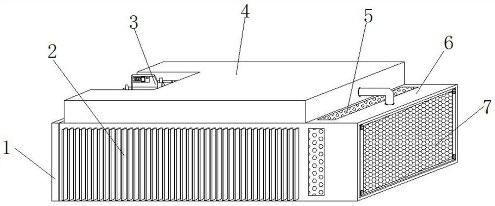
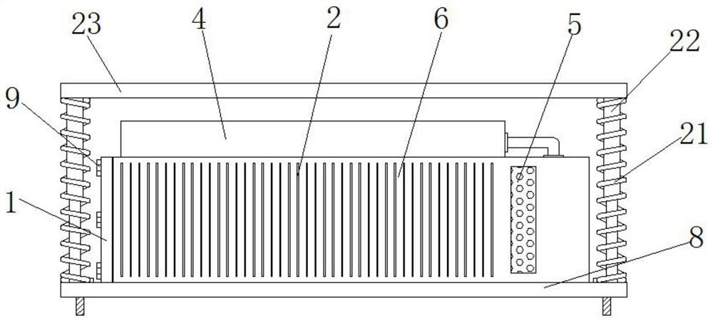
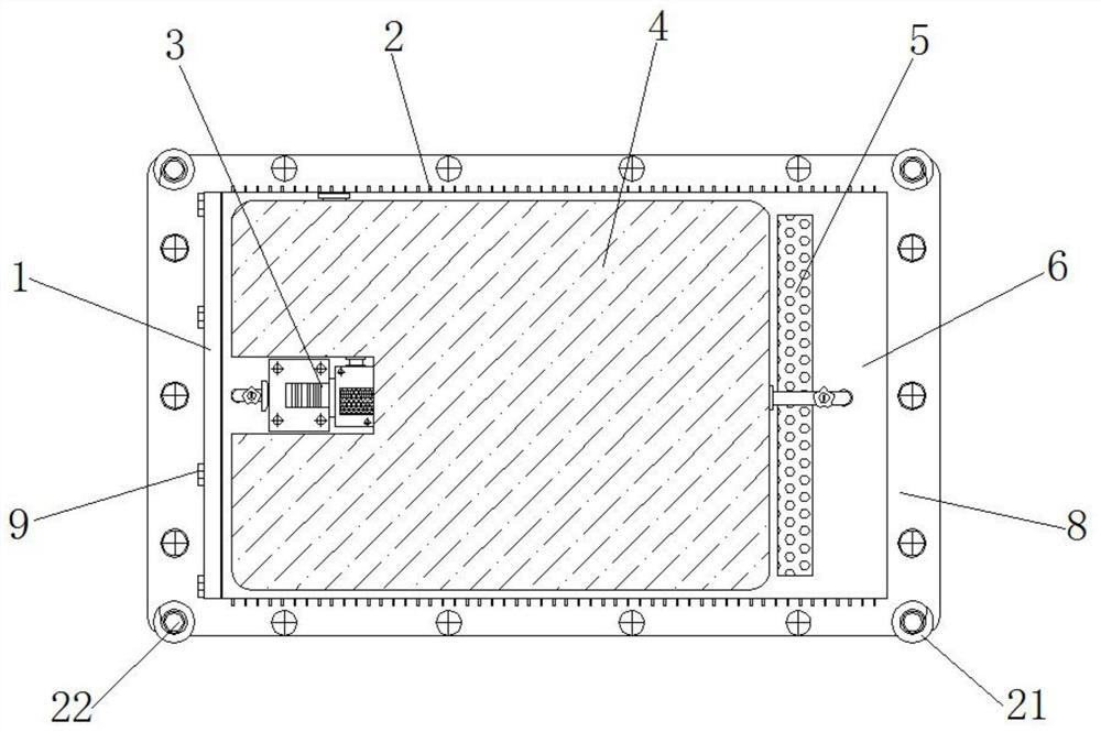
[0039] Example 1, such as Figure 1-5 As shown, when the top of the heat dissipation mechanism is hit, the telescopic rod 22 is shortened, the buffer spring 21 is shortened by force and stores elastic potential energy, and the impact force at the top of the heat dissipation mechanism is buffered. If the bottom of the top plate 23 continues to descend and squeeze to The coolant tank 4, the coolant tank 4 can be used as the second step of buffer protection, and finally the car battery pack 10 can be finally protected through the main body compartment 6, so that when the top of the vehicle is hit, the use of three sets of protective structures can greatly improve the performance of the main body. The safety of the car battery pack 10 inside the compartment 6.

Embodiment 2

[0040] Example 2, such as Figure 1-7 As shown, when the automobile battery pack 10 generates heat during operation, the water pump 3 is controlled by an external control panel to transport the coolant inside the coolant tank 4 to the inside of the heat exchange tube 12, and the coolant passes through the heat exchange tube 12 to enter the cooling In the process inside the tube 14, since the heat exchange tube 12 surrounds the car battery pack 10, the coolant can fully absorb the heat generated by the car battery pack 10, and the heat generated at the end of the car battery pack 10 away from the mounting cover 1 passes through the heat conducting plate 18 is passed to the heat dissipation rod 16, and then two groups of fans 15 are controlled to blow the outside air into the cavity between the filter screen 7 and the partition 17. The group of cooling rods 16 is blown to cool down, and the air with heat is discharged to the external environment through the exhaust hole 5 outsid...


PUM


Abstract

A new energy automobile battery heat dissipation mechanism disclosed in the invention comprises a bottom plate, a main body bin is installed at the top of the bottom plate, a cooling liquid tank is installed at the top of the main body bin, a water pump is installed at one end of the top of the main body bin, and the input end of the water pump communicates with the interior of the cooling liquid tank; and a mounting cover is mounted at the end, close to the water pump, of the main body bin, a spiral groove is formed in the main body bin, a heat exchange pipe is arranged in the spiral groove, and fans are symmetrically mounted on the two sides of the end, away from the mounting cover, in the main body bin. Through cooperative use of the water pump, the cooling liquid box, the spiral groove, the heat exchange pipe, a sieve plate, the fan and a heat conducting plate, the fan can be matched with a heat dissipation pipe to conduct air blowing cooling on cooling liquid passing through the heat dissipation pipe after heat absorption while conducting air blowing cooling on a heat dissipation rod, and through complementation of an air cooling structure and a water cooling structure, the cooling effect of the heat dissipation mechanism on the automobile battery pack can be greatly improved.

Description

technical field [0001] The invention relates to the technical field of new energy vehicles, in particular to a new energy vehicle battery cooling mechanism. Background technique [0002] At present, the energy form and environmental pressure on a global scale are increasingly tense. As a new type of vehicle with the advantages of energy saving, environmental protection, high energy conversion efficiency, and diversified energy sources, new energy vehicles are rapidly developing. Power batteries are used as energy sources for new energy vehicles. , its quality directly affects the safety and service life of the car. During the charging and discharging process of the power battery, the violent chemical reaction inside it will generate a lot of heat, resulting in a sharp change in the battery temperature, and the change of the battery temperature directly affects the battery life. Safety, cycle life, discharge capacity and charge and discharge efficiency and other properties. ...

Claims


Application Information

Patent Timeline
Patent Type & Authority Applications(China)
IPC IPC(8): H01M50/242H01M50/244H01M50/249H01M50/271H01M50/289H01M10/613H01M10/625H01M10/655H01M10/6554H01M10/6556H01M10/6563H01M10/6567
CPCH01M10/613H01M10/625H01M10/655H01M10/6554H01M10/6556H01M10/6563H01M10/6567Y02E60/10
Inventor 不公告发明人
Owner 李晓艳
Why Eureka
Try Eureka