Novel sensorless initial positioning method for switched reluctance motor

A switched reluctance motor and initial positioning technology, which is applied in the control of generators, motor generators, electromechanical brakes, etc., can solve the problem of inaccurate control of the initial conduction phase, power device loss, conduction phase opening, etc. problems, to achieve the effect of improving practicability and universality, improving control accuracy and improving reliability

Pending Publication Date: 2021-06-11
DALIAN UNIV OF TECH
View PDF0 Cites 4 Cited by
  • Summary
  • Abstract
  • Description
  • Claims
  • Application Information

AI Technical Summary

Problems solved by technology

At present, there are two main methods of position sensorless initial positioning based on the pulse injection method: the first is the pulse injection inductance partition method, this method can only determine the range of the rotor position, and it is easy to cause reversal at a position very close to the boundary of the interval start, and the initial conduction phase cannot be accurately controlled; the second is the position estimation method of the switched reluctance motor based on the combination of dual current threshold inductance partition and pulse injection. This method is only suitable for single-shot operation control, and the current threshold Offline manual measurement is required. Different types of motors need to go through the same experimental steps, which takes a lot of time. At the same time, the conduction phase is turned on, the turn-off angle cannot be adjusted, and the pulse injection angle is fixed, resulting in redundant power device losses.

Method used


Image

  • Novel sensorless initial positioning method for switched reluctance motor
  • Novel sensorless initial positioning method for switched reluctance motor
  • Novel sensorless initial positioning method for switched reluctance motor

Examples


Embodiment 1

[0056] Embodiment 1: Take a 12 / 8 pole, 2200r / min, 4.5kW switched reluctance motor as a prototype, with a rated voltage of 60V, an injected voltage pulse frequency of 10kHz, and a duty ratio of 1 / 9. The current sensor adopts a 50A / 5V closed-loop Hall current sensor, and its output is amplified 5.7 times by an operational amplifier and then connected to the AD conversion pin of the microcontroller.

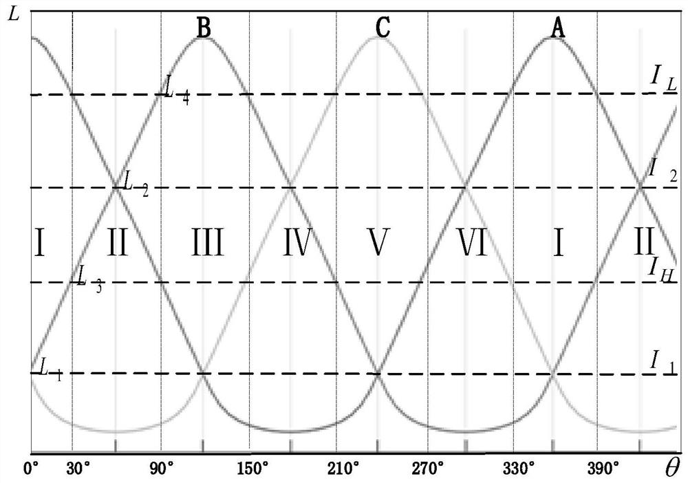
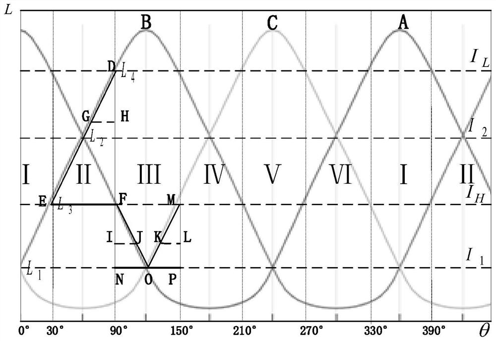
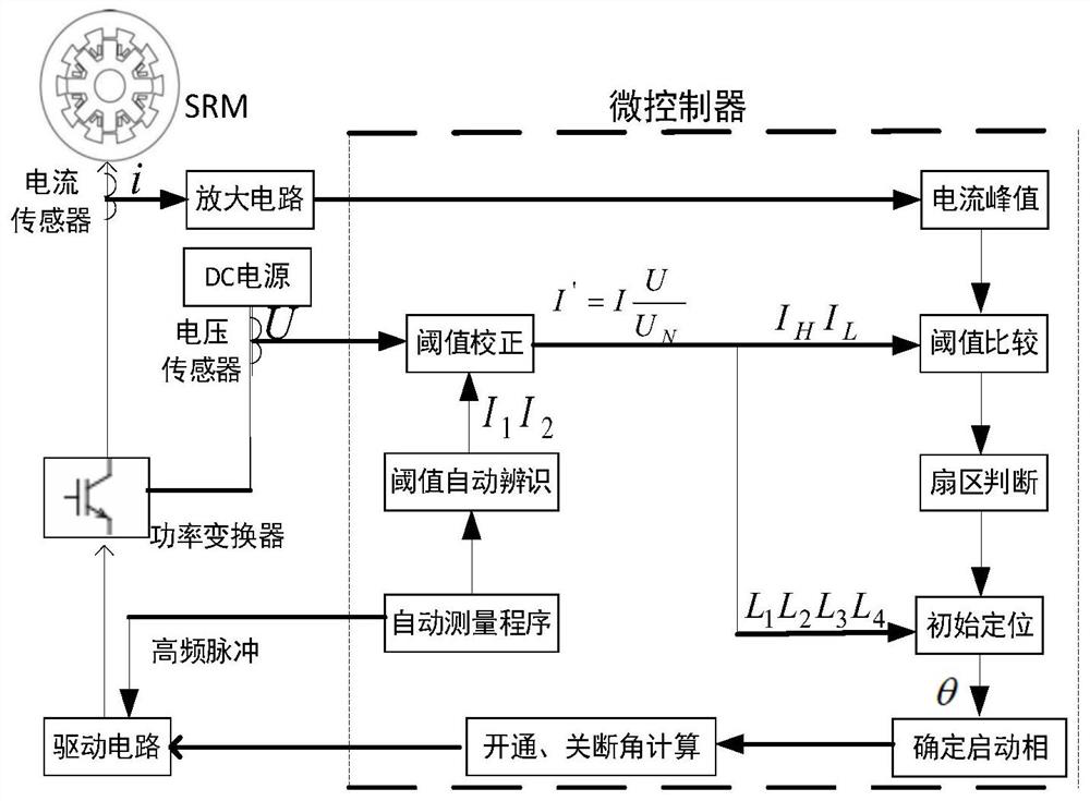
[0057] The specific implementation schematic diagram of the present invention is as image 3 As shown, for different switched reluctance motors, the automatic measurement program is first run at the rated bus voltage, and the voltage pulse with a fixed duty ratio is injected into the three-phase winding through the power converter according to the parameter automatic identification strategy, and the controller collects the current sensor The current signal is used as the feedback current peak value to obtain the response current peak value at the position of the phase inductance int...


PUM


Abstract

The invention provides a novel sensorless initial positioning method of a switched reluctance motor, and belongs to the field of switched reluctance motors. The method comprises the following steps: predicting a feedback current peak value at an intersection point position of two phase inductors through a threshold value automatic identification strategy, and obtaining current threshold values at two special positions according to the height linearization of the inductance of a rotor inductance rising area of the switched reluctance motor; and carrying out the sector judgment and high-precision initial position estimation by comparing the magnitude relationship between a feedback current peak value detected by pulse injection and a corrected current threshold value. According to the method provided by the invention, the initial conduction phase can be accurately controlled, and non-reverse-rotation starting of the motor can be realized; according to the method, the current threshold value is obtained through an automatic measurement program, a large amount of time consumed by manual measurement is avoided, the threshold value is subjected to voltage correction, the influence of voltage fluctuation is effectively overcome, the turn-on angle and the turn-off angle of the turn-on phase during low-speed operation are adjustable, single-beat and double-beat operation can be achieved, and the operation state of the motor is optimized.

Description

technical field [0001] The invention belongs to the field of switched reluctance motors, in particular to a novel position sensorless initial positioning method for switched reluctance motors. Background technique [0002] Switched reluctance motor is a typical brushless double-salient structure motor, and accurate rotor position detection is an important link to ensure its reliable operation. At present, mechanical position sensors such as photoelectric or magnetic sensitive are generally used to detect the position of the rotor, but in an environment with a lot of oil and dust, the detection element of the photoelectric position sensor is very easy to malfunction, resulting in an error in the position signal; the magnetic sensitive position sensor The detection element is extremely susceptible to failure due to interference from magnetic dust and high-frequency electromagnetic fields; in high-temperature environments, the detection element is easily damaged and fails; inte...

Claims


Application Information

Patent Timeline
Patent Type & Authority Applications(China)
IPC IPC(8): H02P21/32H02P6/185
CPCH02P6/185H02P21/32
Inventor 孙建忠王连晟白凤仙
Owner DALIAN UNIV OF TECH
Why Eureka
Try Eureka