Electrochemical hydrogen pump
An electrochemical, single-cell technology, applied in electrochemical generators, circuits, fuel cells, etc., can solve the problems of low pressure, decreased hydrogen pump efficiency, increased resistance, etc., to achieve a lightweight and compact structure, inhibiting The effect of increased contact resistance
- Summary
- Abstract
- Description
- Claims
- Application Information
AI Technical Summary
Problems solved by technology
Method used
Image
Examples
Embodiment approach 1
[0069] use Figure 3A , Figure 3B The electrochemical hydrogen pump 24 according to Embodiment 1 of the present invention will be described. Figure 3A It is a schematic cross section including the cathode inlet and outlet of the electrochemical hydrogen pump 24 of the present embodiment. Figure 3B It is a schematic cross-sectional view including the anode inlet and outlet of the electrochemical hydrogen pump 24 of the present embodiment.
[0070]
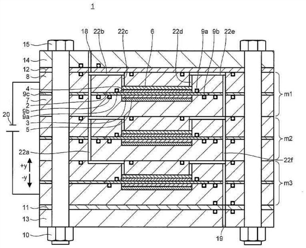
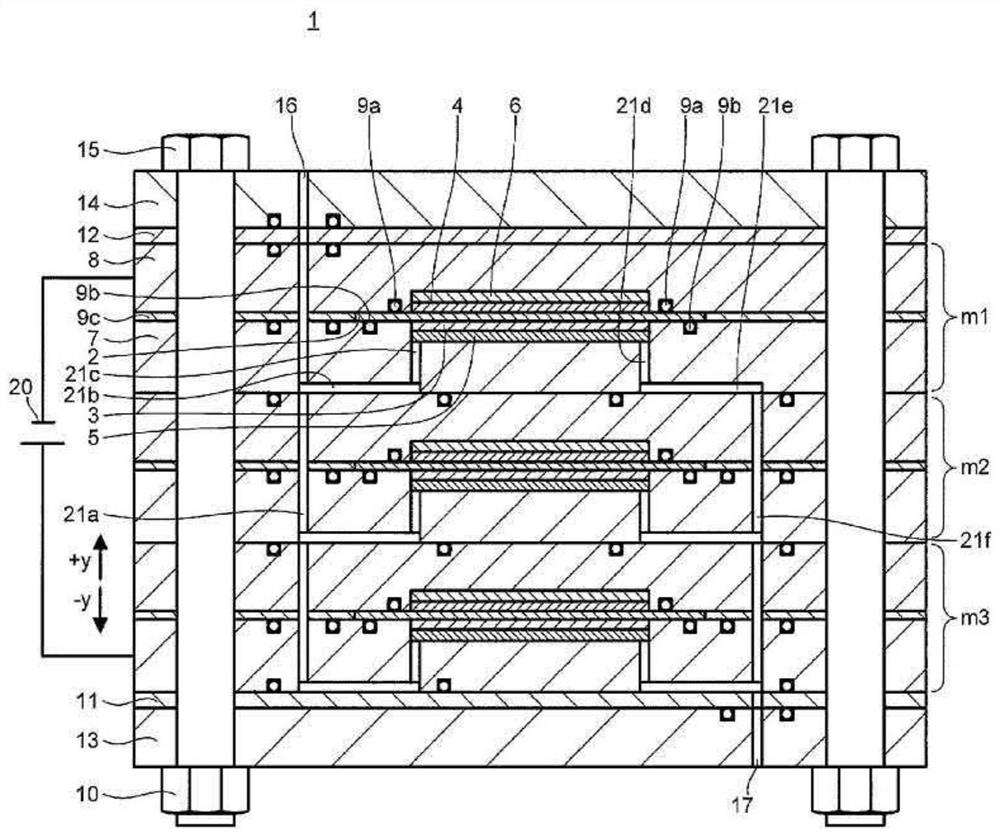
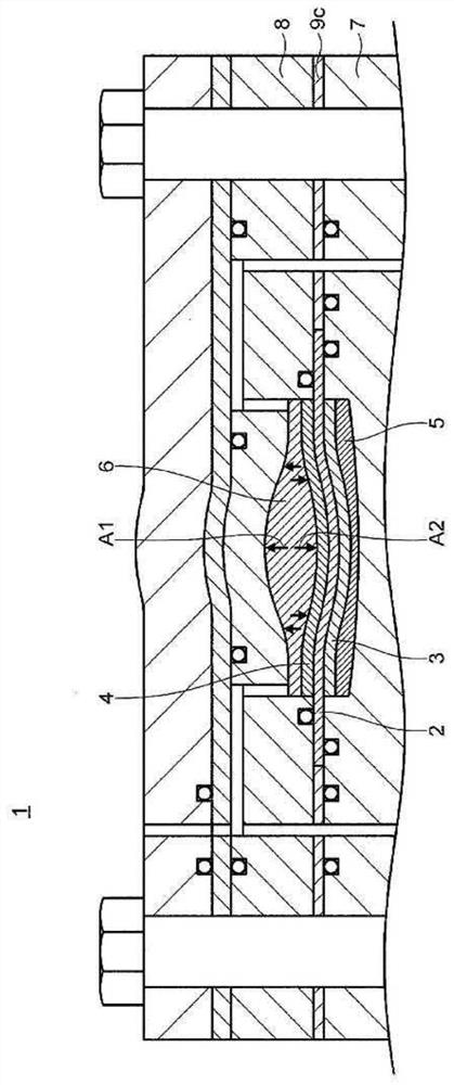
[0071] Figure 3A , Figure 3B The electrochemical hydrogen pump 24 shown with Figure 1A , Figure 1B The illustrated cell stack 1 is similarly stacked with three battery cells m1 , m2 , and m3 .
[0072] The electrochemical hydrogen pump 24 has the following structure, that is, the anode end plate 13, the anode insulating plate 11, the A-end diaphragm 7a, the single cell m3, the single cell m2, and the single cell m1 are sequentially stacked from bottom to top. , C-end diaphragm 8a, C pressure plate 8b, cathode insulati...
Embodiment approach 2
[0148] use Figure 4 The electrochemical hydrogen pump 25 according to Embodiment 2 of the present invention will be described. Figure 4 It is a schematic cross section including the cathode inlet and outlet of the electrochemical hydrogen pump 25 of the present embodiment.
[0149]
[0150] The electrochemical hydrogen pump 25 has a structure in which the anode end plate 13, the anode insulating plate 11, the A-end diaphragm 7a, the battery cell m3, the battery cell m2, and the battery cell m1 are stacked sequentially from bottom to top. , C-terminal diaphragm 8a, cathode insulating plate 12, and cathode end plate 14, these parts are fastened by bolts 15 and nuts 10 in a state of being in close contact with each other.
[0151] An anode pressure space 27 is formed in the anode insulating plate 11 (an example of an anode-side member). In addition, a cathode pressure space 28 is formed in the cathode insulating plate 12 (an example of a cathode-side member).
[0152] The ...
Embodiment approach 3
[0168] use Figure 5 The electrochemical hydrogen pump 26 according to Embodiment 3 of the present invention will be described. Figure 5 It is a schematic cross section including the cathode inlet and outlet of the electrochemical hydrogen pump 26 of the present embodiment.
[0169]
[0170] exist Figure 5 In the electrochemical hydrogen pump 26 shown, three battery cells m1a, m2a, and m3a are stacked.
[0171] The structure of the battery cells m1a, m2a, and m3a will be described.
[0172] The battery cells m1a , m2a , m3a each have an anode separator 7 , an anode diffusion layer 5 , an anode electrode layer 3 , an electrolyte membrane 2 , a seal 9 c , a cathode electrode layer 4 , and a cathode diffusion layer 6 . These constituent elements are the same as those of the electrochemical hydrogen pump 25 according to the first embodiment.
[0173] In this embodiment, each of the battery cells m1a, m2a, and m3a has a first cathode separator 8c and a second cathode separato...
PUM
 Abstract
Description
Claims
Application Information
 - R&D
- Intellectual Property
- Life Sciences
- Materials
- Tech Scout
- Unparalleled Data Quality
- Higher Quality Content
- 60% Fewer Hallucinations
Browse by: Latest US Patents, China's latest patents, Technical Efficacy Thesaurus, Application Domain, Technology Topic, Popular Technical Reports.
© 2025 PatSnap. All rights reserved.Legal|Privacy policy|Modern Slavery Act Transparency Statement|Sitemap|About US| Contact US: help@patsnap.com


