
Low-frequency vibration energy simulation device

A low-frequency vibration and simulation device technology, applied in the direction of fluid, motor-generator control, electrical components, etc., which utilizes vibration, and can solve the problems of small cantilever beam, low efficiency, cantilever beam fracture or deformation, etc.

Pending Publication Date: 2021-06-15
CHINA JILIANG UNIV
View PDF0 Cites 2 Cited by
  • Summary
  • Abstract
  • Description
  • Claims
  • Application Information

AI Technical Summary

Problems solved by technology

The structure uses various electromechanical conversion methods to convert this kinetic energy into electrical energy, but the structure of the cantilever beam itself cannot have too much deformation, so the cantilever beam cannot have too small rigidity, and the quality of the mass block at the end should not be too high. Otherwise, the cantilever beam may break or deform. It is not difficult to see from the vibration system composed of spring and mass block that the efficiency of converting mechanical energy into electrical energy is low. Therefore, it can be seen that the vibration energy simulation device for low frequency It is not yet mature, so a new vibration energy simulation device that solves the above problems is needed in practice

Method used


Image

  • Low-frequency vibration energy simulation device
  • Low-frequency vibration energy simulation device
  • Low-frequency vibration energy simulation device

Examples


Embodiment Construction

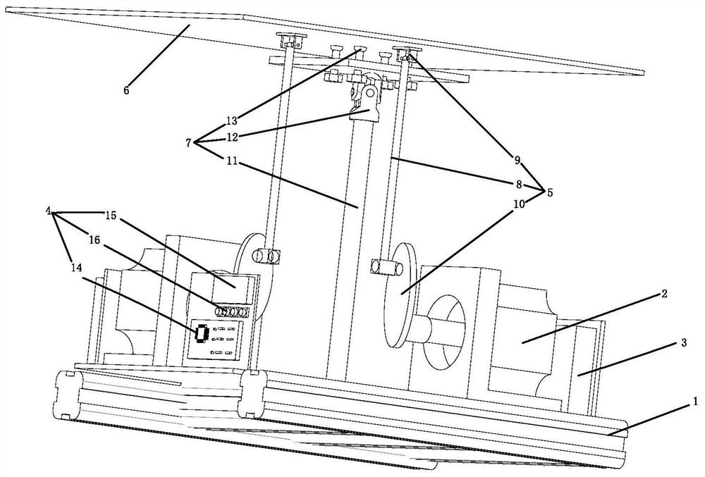
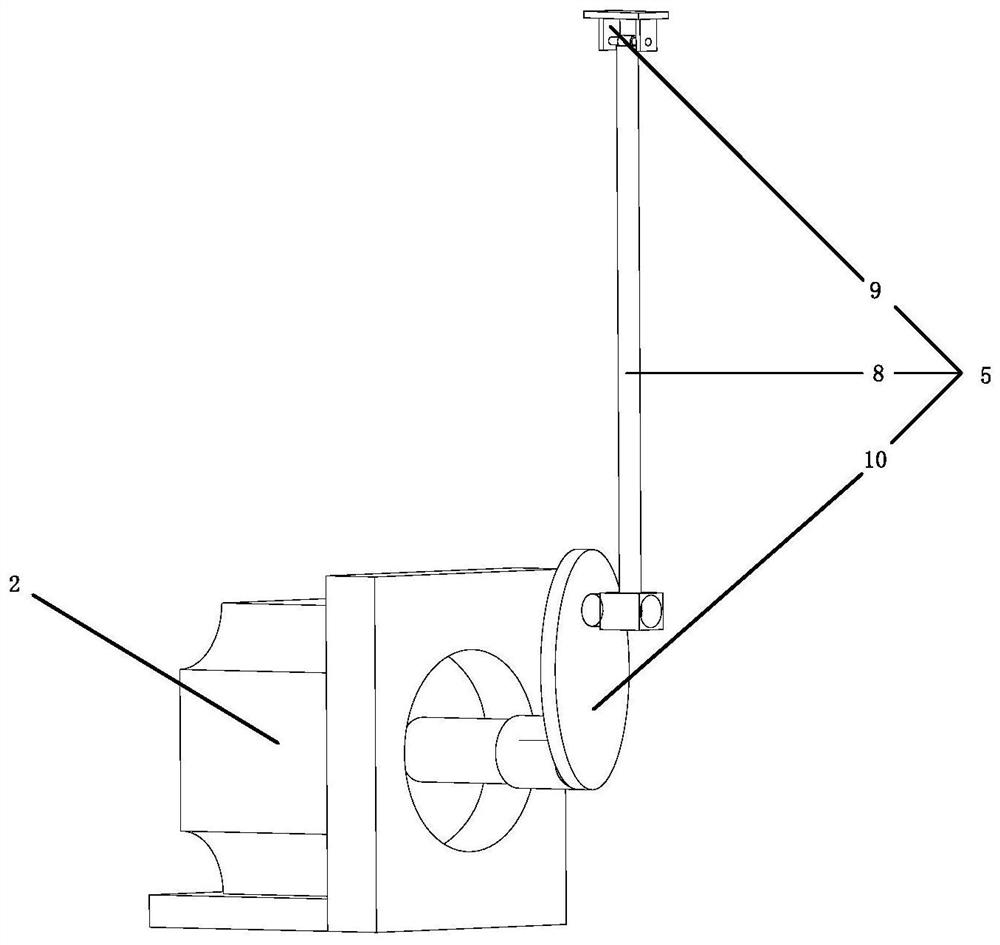
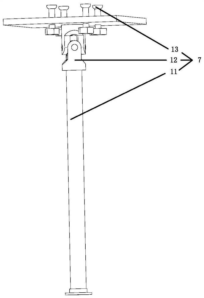
[0015] A low-frequency vibration energy simulation device, comprising a chassis (1), two stepping motors (2), two DC motor drivers (3), a controller (4), two connecting rod structures (5), and an acrylic plate (6) and the support rod structure (7), characterized in that the two stepper motors (2) are fixed on the X-axis and the Y-axis of the chassis (1), such as figure 2 As shown, the connecting rod structure (5) includes a fisheye rod (8), a fixing frame (9) and a crank (10). One end of the fisheye rod (8) is connected to the stepping motor (2) through the crank (10). ), and the other end is connected to the acrylic plate (6) through the fixing bracket (9), such as image 3 As shown, the support rod structure (7) includes a metal straight rod (11), a universal joint (12) and a suction cup (13), and one end of the metal straight rod (11) is connected to the chassis (1), The other end is connected with the suction cup (13) through the universal coupling (12), and the other en...


PUM


Abstract

The invention discloses a low-frequency vibration energy simulation device which comprises a bottom frame, two stepping motors, two direct-current motor drivers, a controller, two connecting rod structures, an acrylic plate and a supporting rod structure; the two stepping motors are fixed to the X axis and the Y axis of the bottom frame; each connecting rod structure comprises a fisheye rod, a fixing frame and a crank; one end of each fisheye rod is connected with the corresponding stepping motor through a crank; the other end of each fisheye rod is connected with the acrylic plate through a fixing frame; the supporting rod structure comprises a metal straight rod, a universal coupling and a suction cup; one end of the metal straight rod is connected with the bottom frame; the other end of the metal straight rod is connected with the suction cup through a universal coupling; the other end of the suction cup is fixed to the center of the acrylic plate; according to the device, a controller is used for setting the rotation frequency of two stepping motors on the X axis and the Y axis; the controller comprises a single chip microcomputer, a display screen and keys; and the stepping motors rotate and drive an acrylic plate to swing in all directions through fisheye rods so as to achieve the effect of simulating external low-frequency vibration.

Description

technical field [0001] The invention belongs to the technical field of vibration energy simulation, and in particular relates to a low-frequency vibration energy simulation device. Background technique [0002] With the development of society and the rapid improvement of scientific and technological level, the demand for energy is also increasing day by day. At present, with the continuous occurrence of energy shortage and environmental pollution, it has begun to affect the economic development of society and people's daily life. Therefore, scientific and technological workers in various countries have gradually begun to focus on the exploration of new energy sources, such as geothermal energy, biomass energy, and wave energy. Vibration is a phenomenon that can be seen everywhere in daily life. Due to its high energy density, its potential energy value has attracted the attention of researchers in many fields. [0003] At present, most of the vibration energy harvesting sim...

Claims


Application Information

Patent Timeline
Patent Type & Authority Applications(China)
IPC IPC(8): B06B1/02H02P8/40H02P8/14
CPCB06B1/02H02P8/14H02P8/40
Inventor 施阁徐苴邴常健曾文涛黄文杰施浙斌林如斌
Owner CHINA JILIANG UNIV
Learn More