Stainless steel band cutting device

A technology for cutting devices and stainless steel strips, which is applied in the direction of shearing devices, accessories for shearing machines, maintenance and safety accessories, etc. It can solve problems such as poor cutting accuracy, easy damage, and steel strips are prone to force deviation, etc. Achieve the effect of avoiding deviation and strong adaptability

Pending Publication Date: 2021-06-15
安徽达顺不锈钢有限公司
View PDF8 Cites 2 Cited by
  • Summary
  • Abstract
  • Description
  • Claims
  • Application Information

AI Technical Summary

Problems solved by technology

[0003] Mechanical vibration is unavoidable during the shearing process of the steel strip, and the steel strip is also easily displaced by force during the shearing process. The above two factors lead to unstable shearing process of the steel strip shearing machine, poor shearing accuracy, and the steel strip The incision is uneven and easily damaged, which greatly affects the product quality
[0004] In addition, there may be scraps or iron filings during the cutting process of the steel strip. If these materials cannot be discharged in time, the cutting accuracy and the incision of the steel strip will be adversely affected in the subsequent cutting process.
Moreover, it is also impossible to realize the recycling of leftovers or iron filings

Method used


Image

  • Stainless steel band cutting device
  • Stainless steel band cutting device
  • Stainless steel band cutting device

Examples


Embodiment 1

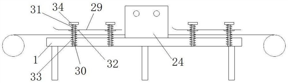
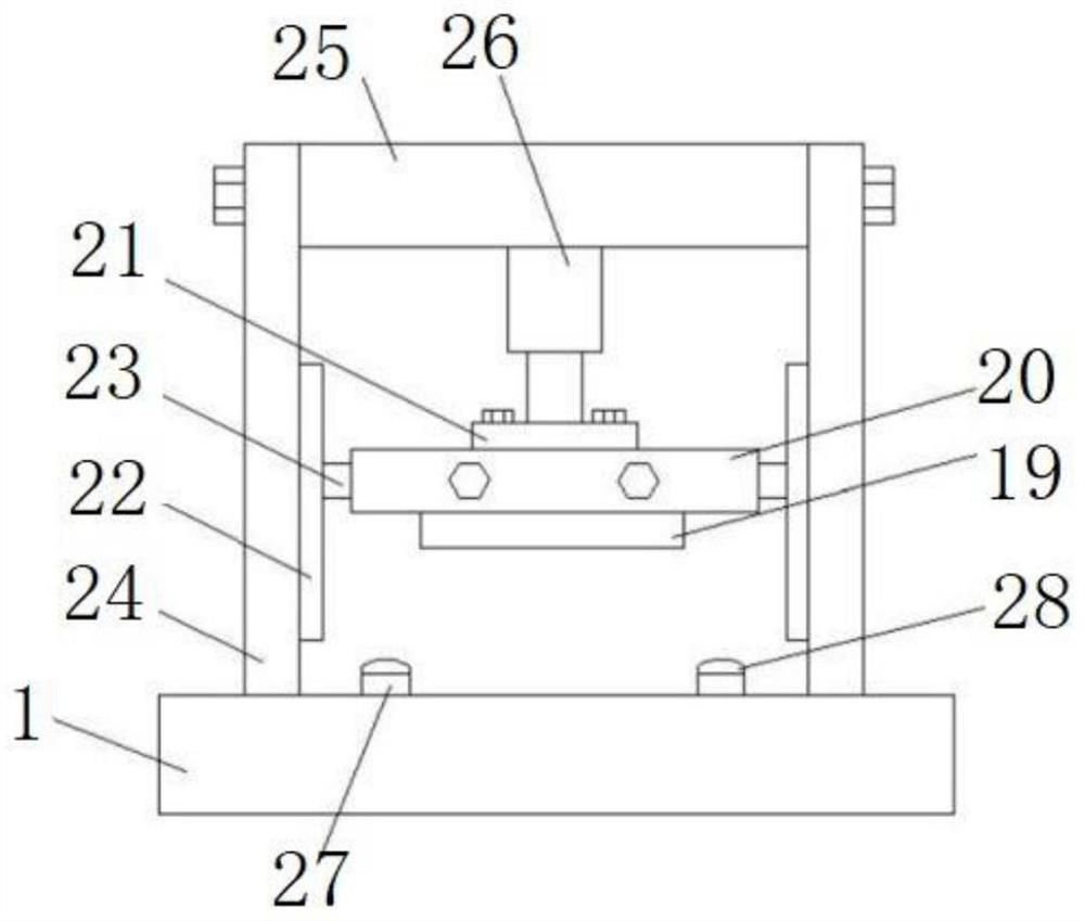
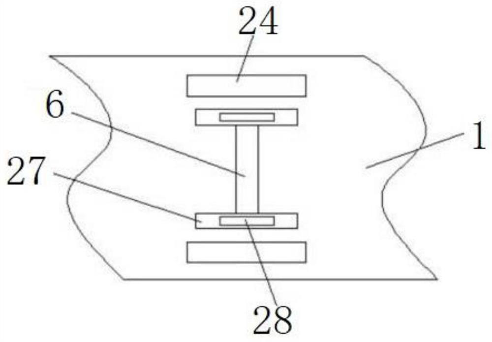
[0031] Such as Figure 1 to Figure 3 As shown, in this embodiment, the steel strip cutting mechanism includes a mounting frame on the working platform, a shearing knife assembly located in the mounting frame, and a lifting mechanism for driving the shearing knife assembly to move up and down to cut the steel strip.

[0032] The shearing knife assembly comprises shearing knife 19 and the knife seat 20 that fixed shearing knife 19 is installed, and described elevating mechanism comprises lifting power part, fixed plate 21, the first chute 22 that is symmetrically arranged on the two sidewalls of the mounting frame and the device For the first sliding block 23 in the first chute 22 , the two ends of the fixing plate 21 are respectively connected to the two first sliding blocks 23 , and the tool holder 20 is connected to the lifting power component through the fixing plate 21 . The lifting power components can be hydraulic cylinders, air cylinders or electric push rods, and this e...

Embodiment 2

[0041] Such as Figure 4 with Figure 5As shown, the difference between this embodiment and Embodiment 1 is that a recovery box is provided below the cutting groove on the working platform, and the inlet of the recovery box is located directly below the cutting groove. One side of the upper surface of the recovery box is provided with a fixed door 3, and the two relative side walls of the front side wall and the rear side wall in the recovery box 2 are all provided with a limit guide rail 16, and the limit guide rail 16 is arranged in parallel with the fixed door 3, and the position limit Guide rail 16 is arranged below fixed door 3, and the other side of recovery box 2 upper surface is provided with movable door 4, and the width of movable door 4 is less than the width of described fixed door 3, and described movable door 4 and described recovery box 2 pass through The limit guide rail 16 is slidingly connected, the upper end of the fixed door 3 is hinged with a spring plate...


PUM


Abstract

The invention provides a stainless steel band cutting device which comprises a working platform; the working platform is provided with a steel band cutting mechanism used for cutting a steel band, a first elastic pressing and positioning mechanism and a second elastic pressing and positioning mechanism; the first elastic pressing and positioning mechanism and the second elastic pressing and positioning mechanism are arranged on the two sides of the steel band cutting mechanism and used for elastically extruding and positioning the steel band; the two sides of the cut steel belt can be limited; the situation that the steel belt deviates in the cutting process, and the shearing precision is affected is avoided; the distance between the pressing plate and the pressing cover of the working platform is elastically adjusted; limiting of steel belts with different thicknesses can be achieved; and adaptability is higher.

Description

technical field [0001] The invention relates to the technical field of steel strip processing, in particular to a stainless steel strip cutting device. Background technique [0002] Steel belt refers to the conveyor belt made of carbon steel as the traction and carrying member of the belt conveyor, and can also be used to bundle goods. It is a kind of steel belt that various steel rolling enterprises need to meet the industrial production of various metal or mechanical products in different industrial sectors. A narrow and long steel plate produced. [0003] Mechanical vibration is unavoidable during the shearing process of the steel strip, and the steel strip is also easily displaced by force during the shearing process. The above two factors lead to unstable shearing process of the steel strip shearing machine, poor shearing accuracy, and the steel strip The incision is uneven and easily damaged, which greatly affects the product quality. [0004] Furthermore, there may ...

Claims


Application Information

Patent Timeline
Patent Type & Authority Applications(China)
IPC IPC(8): B23D15/04B23D33/02B23D15/14B23Q11/00
CPCB23D15/04B23D33/02B23D15/14B23Q11/00
Inventor 刘标陆龙根
Owner 安徽达顺不锈钢有限公司
Why Eureka
Try Eureka