
Method for measuring electron energy distribution curve at collector inlet of traveling wave tube

A technology of electron energy and distribution curve, applied in vacuum tube testing and other directions, can solve the problems of restricting traveling wave tubes, high design cost, and long design cycle for improving collector efficiency, so as to reduce development costs, facilitate operation, and reduce the number of iterative development. and the effect of the design cycle

Active Publication Date: 2021-06-15
UNIV OF ELECTRONICS SCI & TECH OF CHINA
View PDF8 Cites 2 Cited by
  • Summary
  • Abstract
  • Description
  • Claims
  • Application Information

AI Technical Summary

Problems solved by technology

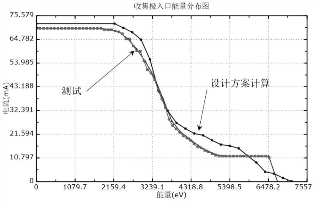
[0006] In view of the above-mentioned problems or deficiencies, in order to solve the defects that there is a large difference between the design of the high-efficiency collector of the existing traveling wave tube and the actual manufacturing, which seriously restricts the improvement of the efficiency of the collector of the traveling wave tube, the long design cycle and the large design cost, this paper The invention proposes a method for measuring the electron energy distribution curve at the collector inlet of a traveling wave tube. By using this method, the electron energy distribution curve at the collector inlet can be measured. The measured energy distribution curve at the collector inlet is more accurate than the simulated data. Therefore, it can effectively guide the design of high-efficiency collectors

Method used

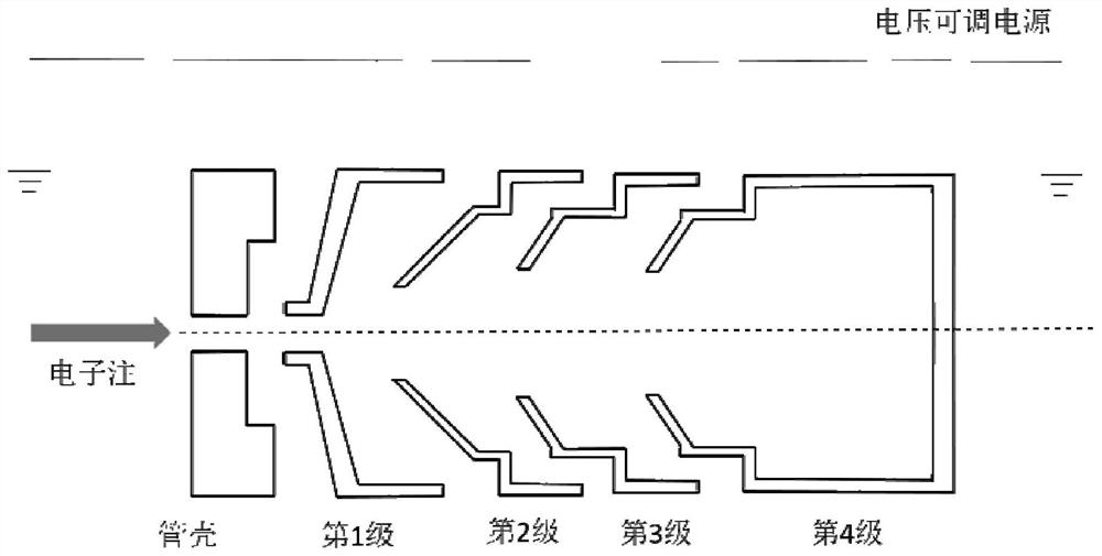
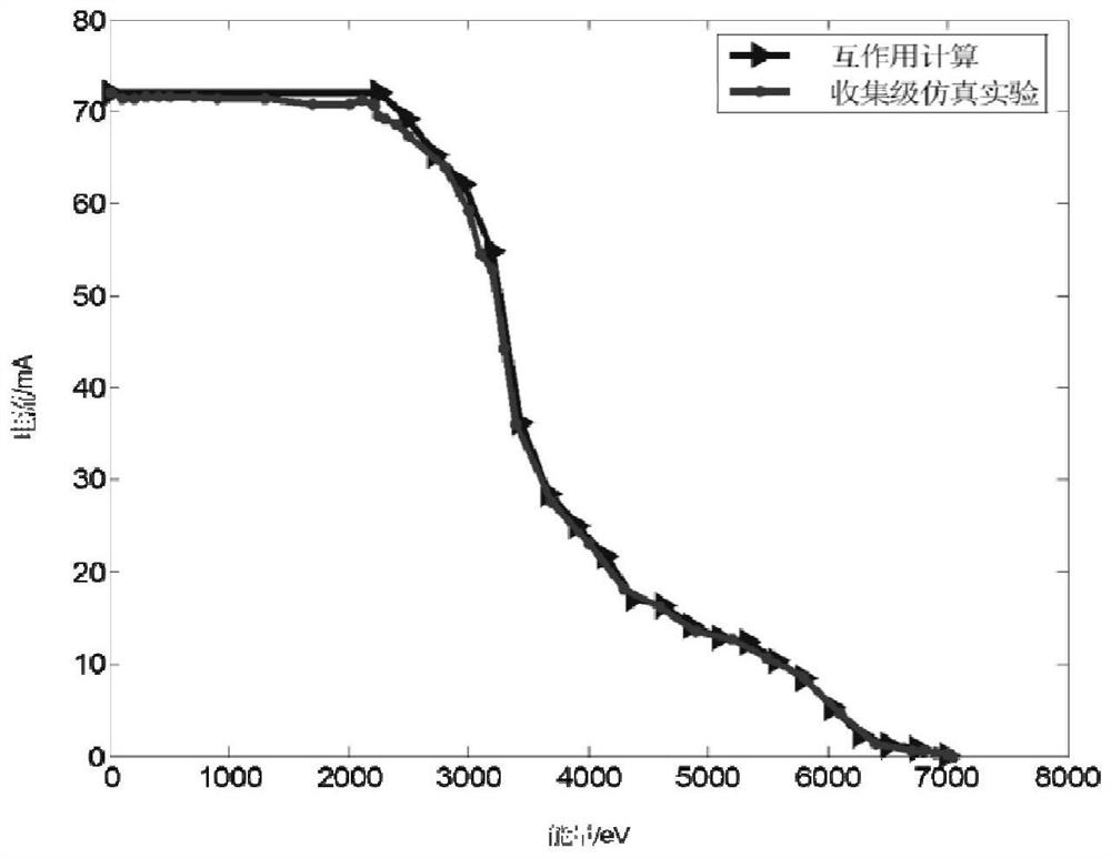

Image

  • Method for measuring electron energy distribution curve at collector inlet of traveling wave tube
  • Method for measuring electron energy distribution curve at collector inlet of traveling wave tube
  • Method for measuring electron energy distribution curve at collector inlet of traveling wave tube

Examples


Embodiment Construction

[0032] The present invention will be further described in detail below in conjunction with a space traveling wave tube four-stage step-down collector.

[0033] Step 1 Description:

[0034] Connect the traveling wave tube power supply, the input signal input device and the output signal receiving device, set the working ratio of the traveling wave tube electron injection modulation power supply to 1%-5%, and set the traveling wave tube spiral flow safety threshold I h , given the recovery current indication value I of the stop voltage step-down sweep R .

[0035] For the measurement data of the traveling wave tube, the first step is to add power to the traveling wave tube and input signal input device and output signal receiving device. Make sure the TWT is working properly. In order to ensure safety, the TWT electronic injection modulation power supply is tested from a low duty ratio, and the duty ratio range of 1%-5% is selected here; the initial duty ratio is set to 5% in...


PUM


Abstract

The invention belongs to the technical field of traveling wave tube high efficiency, and particularly relates to a method for measuring an electron energy distribution curve at a collector inlet of a traveling wave tube. The traveling wave tube is tested through low-work-ratio electron beam emission, on the premise that safety is guaranteed, the work ratio of the traveling wave tube is gradually increased till the work ratio of the traveling wave tube cannot be continuously increased, and at the moment, measurement data are final measurement data. And the final measurement data is used for guiding the iterative optimization design and debugging of a high-efficiency collector, so that the iterative development times and the design period of the development of the high-efficiency traveling wave tube are reduced, and the development cost of the high-efficiency traveling wave tube is reduced favourably. Moreover, the method is convenient and simple to operate, a complicated test system does not need to be manufactured, and time and experiment cost are greatly saved.

Description

technical field [0001] The invention belongs to the high-efficiency technical field of traveling wave tubes, and in particular relates to a method for measuring electron energy distribution curves at the inlet of a traveling wave tube collector. Background technique [0002] Traveling wave tubes are broadband and high-power vacuum electronic devices with high efficiency, large bandwidth, high reliability, long life and radiation resistance, and are widely used in radar, satellite communication, navigation and other fields. High efficiency is one of the development goals of traveling wave tubes. High efficiency means that the energy conversion efficiency of traveling wave tubes is high. Under the limited energy supply of traveling wave tubes, it helps to save system energy; it also means that in the same With a high energy supply, the satellite payload can be increased; high efficiency also means low energy loss, and the heat energy converted from the electrical energy lost b...

Claims


Application Information

Patent Timeline
IPC IPC(8): G01R31/25
CPCG01R31/25
Inventor 王小兵胡权邓文凯朱世龙高鸾凤胡玉禄朱小芳李斌杨中海
Owner UNIV OF ELECTRONICS SCI & TECH OF CHINA
Learn More