A laser marking device for rubber tire production

A technology of laser marking and rubber tires, applied in laser welding equipment, metal processing equipment, welding equipment, etc., can solve the problems of limited marking range and reduced marking efficiency, so as to improve marking efficiency and achieve good marking effect , Ensure the effect of the production environment

Active Publication Date: 2021-07-30
SHANDONG LINGLONG TIRE
View PDF1 Cites 0 Cited by
  • Summary
  • Abstract
  • Description
  • Claims
  • Application Information

AI Technical Summary

Problems solved by technology

[0003] At present, the Chinese patent with the publication number CN201566212U discloses a tire laser marking device, which includes an assembly line conveyor belt, a clamping and rotating device, an information collection work area, a tire data reader, a marking position reader, and auxiliary lighting. Equipment, smoke extraction equipment, laser marking work area, smoke filtration and exhaust equipment, radio frequency CO2 laser, focusing table, high-speed laser scanner, scanning focusing mirror, collimating beam expander system, mirror and computer system, the The patent adopts machine vision recognition technology, which can automatically judge the marking position according to the different shapes and arrangement positions of tires on the assembly line and guide the beam scanner to accurately locate. It does not need special mechanical or manual marking and positioning devices, and can realize seamless connection with the tire production line. , which improves the processing efficiency of the equipment, but it needs to use the assembly line conveyor belt to transport the tires, while the laser marking machine needs to stop the conveyor belt work when performing the marking operation, thus reducing the marking efficiency. The marking operation is carried out on one side, and the marking range is relatively limited

Method used


Image

  • A laser marking device for rubber tire production
  • A laser marking device for rubber tire production
  • A laser marking device for rubber tire production

Examples


Embodiment Construction

[0034] The present invention will be further described below in conjunction with the examples.

[0035] The following examples are used to illustrate the present invention, but cannot be used to limit the protection scope of the present invention. The conditions in the embodiment can be further adjusted according to the specific conditions, and the simple improvement of the method of the present invention under the premise of the concept of the present invention belongs to the protection scope of the present invention.

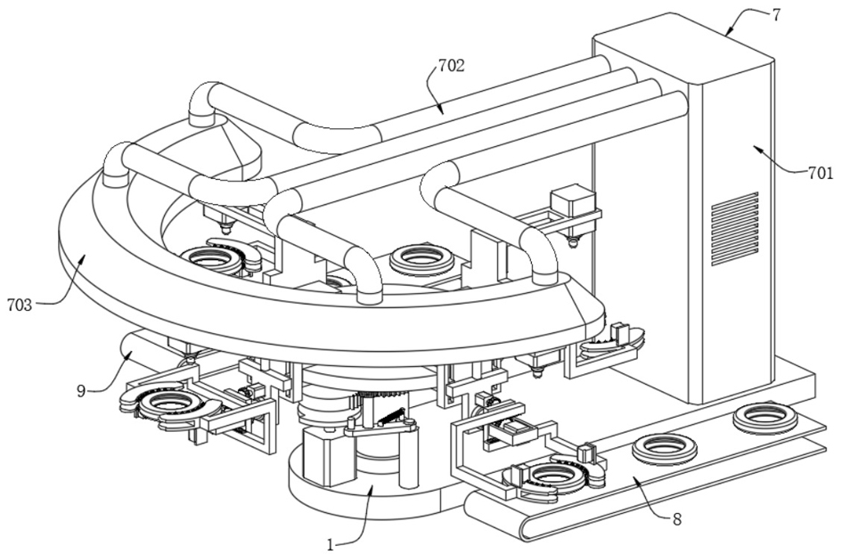
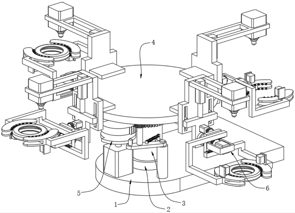
[0036] see Figure 1-8 , the present invention provides a laser marking device for rubber tire production, comprising a base plate 1, a rotating shaft 3 is rotatably connected to the base plate 1 through a bearing seat 2, and a rotating disk 4 is fixedly connected to the top of the rotating shaft 3;

[0037] Braking intermittent mechanism 5, the braking intermittent mechanism 5 is fixed on the bottom plate 1, the braking intermittent mechanism 5 is used to ma...


PUM


Abstract

The invention discloses a laser marking device for rubber tire production, which belongs to the technical field of tire production equipment, and comprises a bottom plate. The bottom plate is connected with a rotating shaft 1 through the rotation of a bearing seat 1, and a rotating disk is fixedly connected to the top of the rotating shaft 1. ; The intermittent braking mechanism is fixed on the bottom plate, and the intermittent braking mechanism is used to make the rotating disc rotate intermittently, and provide a braking effect after the rotating disc rotates, so as to prevent the rotating disc from being damaged due to inertia. Continue to rotate; the double-sided marking clamping mechanism has four double-sided marking clamping mechanisms, and the four double-sided marking clamping mechanisms are fixed on the outer wall of the rotating disk in equal parts. The clamping mechanism is used to complete the grabbing action of the tire and carry out the laser marking work on both sides of the tire; avoid the problem that the tire cannot be transported during the marking process, improve the marking efficiency of the tire, and at the same time carry out the marking on both sides of the tire Marking work, better marking effect.

Description

technical field [0001] The invention belongs to the technical field of tire production equipment, and in particular relates to a laser marking device for rubber tire production. Background technique [0002] Tires are ground-rolling circular elastic rubber products assembled on various vehicles or machinery. They are usually installed on metal rims, which can support the body, buffer external impact, realize contact with the road surface and ensure the driving performance of the vehicle. Tires are often Used under complex and harsh conditions, it is subjected to various deformations, loads, forces, and high and low temperature effects during driving, so it must have high load-bearing performance, traction performance, and cushioning performance. At the same time, it also requires high wear resistance. and flex resistance, as well as low rolling resistance and heat generation. [0003] At present, the Chinese patent with the publication number CN201566212U discloses a tire l...

Claims


Application Information

Patent Timeline
Patent Type & Authority Patents(China)
IPC IPC(8): B23K26/362B23K26/16B23K26/02B23K26/08
CPCB23K26/02B23K26/0823B23K26/16B23K26/362
Inventor 王锋孙松涛李彦果马玉静张琦罗洪罡鲁国熹卞在愿
Owner SHANDONG LINGLONG TIRE
Why Eureka
Try Eureka