Grouting device for controlling settlement of height railroad bed and grouting method

A technology of grouting device and railway subgrade, which is applied in the direction of road, soil protection, infrastructure engineering, etc., can solve the problems of large variation of grouting pressure, large equipment vibration, inability to accurately control grouting pressure, etc., to reduce vibration , the effect of improving uniformity

Active Publication Date: 2021-06-18
CHINA RAILWAY ENG CONSULTING GRP CO LTD
View PDF4 Cites 2 Cited by
  • Summary
  • Abstract
  • Description
  • Claims
  • Application Information

AI Technical Summary

Problems solved by technology

[0004] During the grouting process of the grouting equipment, the grouting pressure of the grouting machine is in a dynamic change process, which leads to a large change in the grouting pressure. Not only the vibration of the equipment is large, but also the grouting pressure cannot be accurately controlled, which is easy cause formation changes

Method used


Image

  • Grouting device for controlling settlement of height railroad bed and grouting method
  • Grouting device for controlling settlement of height railroad bed and grouting method
  • Grouting device for controlling settlement of height railroad bed and grouting method

Examples


Embodiment approach 1

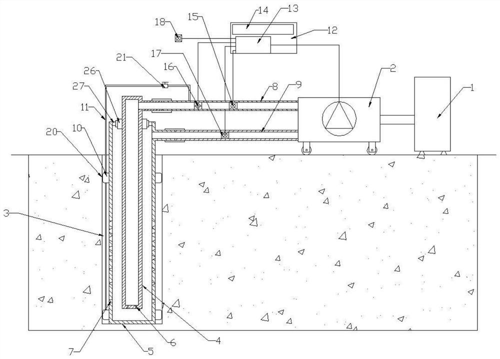
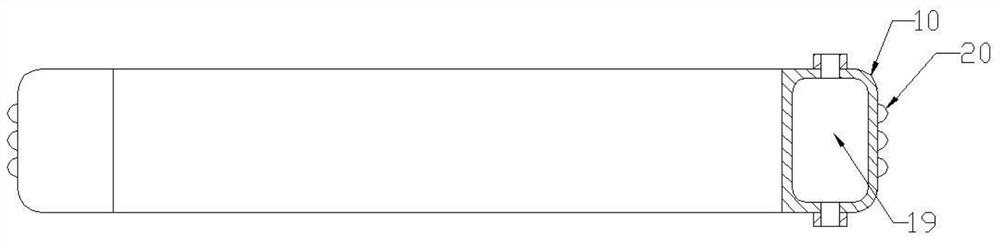
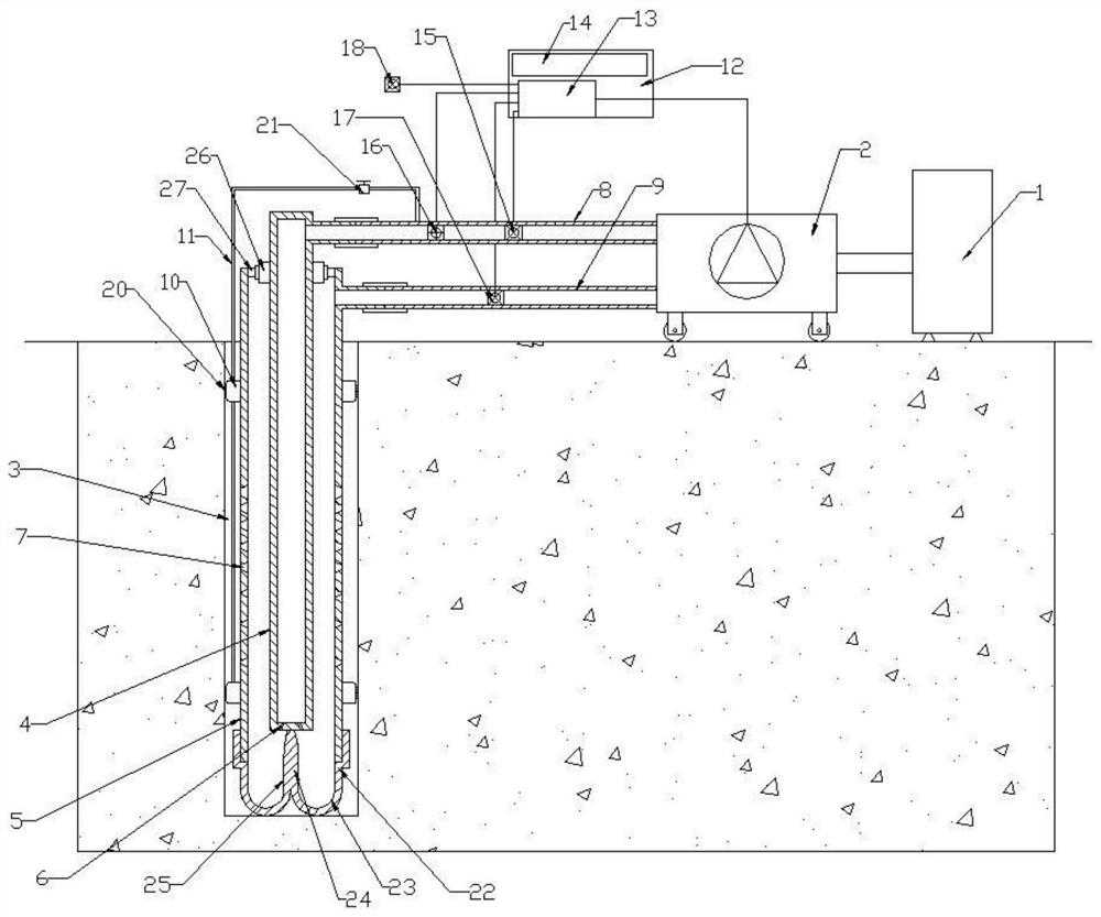
[0048] Such as figure 1 with figure 2 As shown, this embodiment provides a double-layer self-circulating pressure-maintaining grouting device, including a grouting machine 1, a grouting pump 2 and a grouting pipe 3, and the grouting pump 2 is communicated with the grouting machine 1, so that The grouting pipe 3 includes an inner pipe 4 and an outer pipe 5. The top of the inner pipe 4 is fixedly provided with a fixed disk 26, and the two ends of the outer pipe 5 are open structures, and a fixed ring 27 is arranged at the upper open end. The fixed disk 26 and The fixing ring 27 is threaded and connected, so that the outer pipe 5 is placed on the outer surface of the inner pipe 4; the top of the inner pipe 4 is connected with the connecting pipe 8, and the upper part of the outer pipe 5 sidewall is connected with a circulation pipe 9, and the connecting pipe 8 And the circulation pipe 9 is connected with the outlet and return port of the external grouting pump 2, thereby formin...

Embodiment approach 3

[0054] This embodiment, as another basic embodiment of the present invention, discloses a grouting method for controlling the settlement of a high-grade railway embankment: comprising the following steps:

[0055] S1. Drill the grouting pipe installation holes from both sides of the high-speed railway subgrade to the grouting area directly below the subgrade; and ensure that the grouting pipe installation holes on the left and right sides are drilled alternately;

[0056] S2. Install the grouting pipes in the grouting pipe installation holes, and at the same time group the grouting pipes according to the requirements of the grouting pressure and equipment power, and connect the same group of grouting pipes to the same set of grouting devices;

[0057] S3. Drill a monitoring hole from one side of the railway subgrade. The terminal of the monitoring hole is located between the Pearl River area and the subgrade; install the soil deformation monitoring sensor in the monitoring hole...


PUM


Abstract

The invention relates to a grouting device for controlling settlement of a height railway roadbed and a grouting method. The grouting device for controlling the settlement of the height railway roadbed comprises a pulping machine, a grouting pipe and a grouting pump, wherein the grouting pipe comprises an inner pipe and an outer pipe which sleeve with each other, the inner pipe and the outer pipe communicate with each other, and grout outlet holes are formed in the outer pipe; meanwhile, the inner pipe and the outer pipe are connected with the grouting pump through a communicating pipe and a circulating pipe correspondingly; meanwhile, the outer pipe further sleeves with an expansion sleeve, and the expansion sleeve is connected with the communicating pipe through an expansion pipe. According to the grouting device for controlling the settlement of the height railway roadbed, slurry is buffered through the design of the inner pipe and the outer pipe, so that the pressure change amplitude of the slurry is reduced; meanwhile, drainage is conducted to the far end of the grouting pipe through adjustment of the hole diameter and the distribution density of the grout outlet holes, and therefore uniform distribution of grout is guaranteed; the grouting pipe is fixed in a mounting hole after the expansion sleeves at the two ends of the grouting pipe are expanded, so that the vibration of the grouting pipe is further reduced, and the grouting quality is improved; an inlet and an outlet of the grout are formed in the top of the grouting pipe, the grouting pipe can be installed at any angle, and the application range of the grouting pipe is expanded.

Description

technical field [0001] The invention relates to the technical field of railway construction, in particular to a grouting device and a grouting method for controlling the settlement of a high-level railway embankment. Background technique [0002] The grouting method is to use the pressure (hydraulic pressure, air pressure) or electrochemical principle to uniformly inject the grout with gel ability into the gaps, cracks and cavities in the soil layer (or rock layer) through drilling holes, and the grout can fill, infiltrate and The original loose and broken rock (soil) layer is cemented into a whole by means of extrusion, and the physical and mechanical properties of the rock (soil) layer (such as the permeability of rock and soil layers, The strength and bearing capacity of rock and soil layers, the deformation of rock and soil layers, etc.) can be improved to form a structure with new structure, high strength, high waterproof performance and good chemical stability to meet ...

Claims


Application Information

Patent Timeline
Patent Type & Authority Applications(China)
IPC IPC(8): E02D3/12E01B2/00
CPCE02D3/12E01B2/00E01B2204/03
Inventor 刘建友刘方岳岭吕刚谭富圣马福东金张澜王文谦徐品章陈丹康佩彭斌王杨郭磊陈慧李力张延张矿三
Owner CHINA RAILWAY ENG CONSULTING GRP CO LTD
Why Eureka
Try Eureka