Small automatic loose sand barreling machine

A barrel loading machine and automatic technology, which is applied in the direction of motor vehicles, storage devices, loading/unloading, etc., can solve the problems of different convenience and work efficiency of sand removal devices, and achieve ingenious structural settings, high work efficiency, and easy operation. convenient effect

Pending Publication Date: 2021-06-18
吴良辉
View PDF6 Cites 0 Cited by
  • Summary
  • Abstract
  • Description
  • Claims
  • Application Information

AI Technical Summary

Problems solved by technology

[0009] After research, it is found that different structures are different in convenience and work efficiency of sand removal devices.

Method used


Image

  • Small automatic loose sand barreling machine
  • Small automatic loose sand barreling machine
  • Small automatic loose sand barreling machine

Examples


Embodiment 1

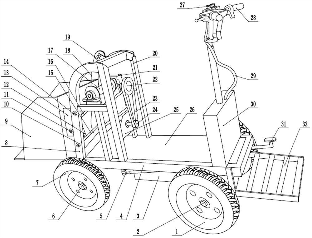
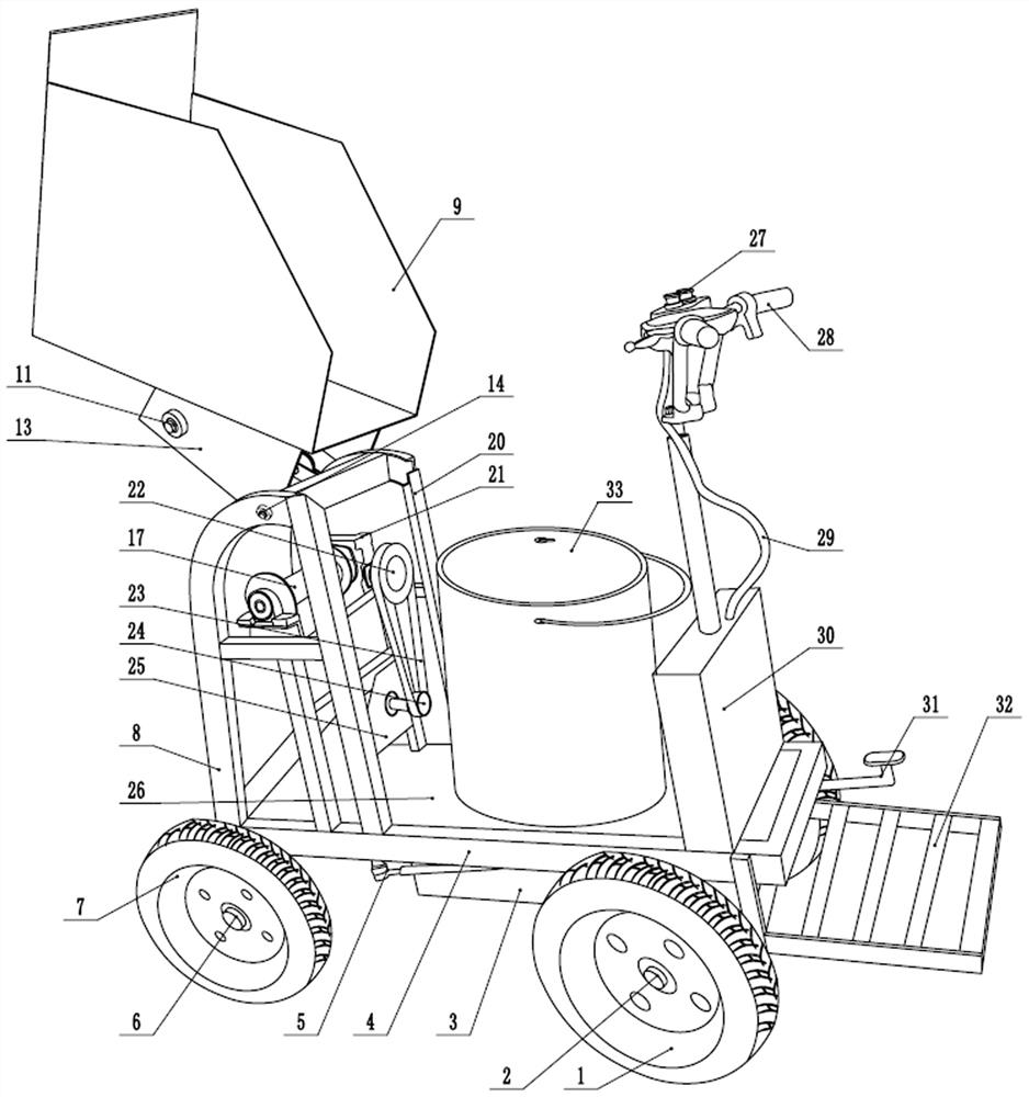
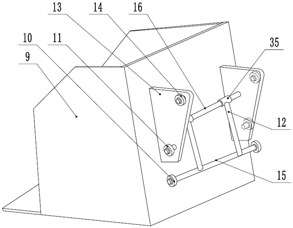
[0027] A small automatic loose sand barreling machine, which includes a frame 4 and a bucket 9, the lower part of the front end and the rear end of the frame 4 are correspondingly installed with a front axle 6 with a front wheel 7 and a rear wheel 1 The electric rear axle 2; the upper front end of the vehicle frame 4 is provided with a bracket 20, a slide rail 8 is respectively provided on both sides of the front end of the bracket 20, and a slide groove 34 is respectively provided on the opposite sides of the two slide rails 8; A fixed pulley 19 is installed on the upper front end of the bracket 20; a vertically arranged supporting connecting plate 13 is respectively arranged on both sides of the back of the bucket 9, and a supporting connecting rod 16 is fixedly connected between the two supporting connecting plates 13, Connecting sleeve 35 is sleeved on the supporting connecting rod 16, and connecting sleeve 35 is fixedly connected with mounting rod 15 by connecting rod 12. ...

Embodiment 2

[0029] A small automatic loose sand barreling machine, which includes a frame 4 and a bucket 9, the lower part of the front end and the rear end of the frame 4 are correspondingly installed with a front axle 6 with a front wheel 7 and a rear wheel 1 The electric rear axle 2; the upper front end of the vehicle frame 4 is provided with a bracket 20, a slide rail 8 is respectively provided on both sides of the front end of the bracket 20, and a slide groove 34 is respectively provided on the opposite sides of the two slide rails 8; A fixed pulley 19 is installed on the upper front end of the bracket 20; a vertically arranged supporting connecting plate 13 is respectively arranged on both sides of the back of the bucket 9, and a supporting connecting rod 16 is fixedly connected between the two supporting connecting plates 13, Connecting sleeve 35 is sleeved on the supporting connecting rod 16, and connecting sleeve 35 is fixedly connected with mounting rod 15 by connecting rod 12. ...


PUM


Abstract

The invention provides a small automatic loose sand barreling machine. The small automatic loose sand barreling machine comprises a frame and a bucket, wherein a front axle assembly and an electric rear axle assembly are mounted at the lower part of the frame; a bracket is arranged at the upper part of the front end of the frame; a slide rail is arranged on each of the two sides of the front end of the bracket; the two slide rails are provided with slide grooves; a fixed pulley is mounted at the upper part of the front end of the bracket; a slide mechanism capable of sliding on the slide rails is mounted at the back part of the bucket; an electric winch is mounted on the bracket; one end of a steel wire rope wound on the electric winch is connected with the slide mechanism after bypassing the fixed pulley; the electric winch controls the bucket to slide up and down along the slide rails and to backwards topple over at the top ends of the slide rails; a cushion plate for placing a sand barreling barrel is mounted on the frame; a storage battery box is mounted on the frame at the lower part of the cushion plate; a steering handle and a controller box are mounted at the rear end of the frame; the steering handle is connected with a connecting rod steering mechanism; and a control key for controlling the electric winch and a motor of an electric rear axle to work is mounted on the steering handle. The barreling machine can automatically shovel sand and fill sand through, and is high in working efficiency.

Description

technical field [0001] The invention relates to the technical field of building construction tools, in particular to a small-sized automatic loose sand barreling machine. Background technique [0002] During building construction, sand is needed to make concrete or other construction projects, but the sand is piled up together. In the process of transporting sand in general construction sites, it needs to be loaded into sand buckets for transportation. Usually construction The personnel use shovels to shovel the sand into the sand bucket. People need to constantly swing the shovels, which is time-consuming and labor-intensive. After a long time, the construction workers' arms are prone to soreness and affect the follow-up work. Therefore, people have developed sand-shoveling devices, and open literature has also reported some sand-shoveling devices, such as: [0003] 1. Chinese patent: a bulk sand barreling machine, application number: 201910352014.2, application date: 2019...

Claims


Application Information

Patent Timeline
IPC IPC(8): E04G21/00B65G65/32B65G63/00B62D63/04B62D51/02B62D51/00
CPCE04G21/00B65G65/32B62D51/001B62D51/02B62D63/04B65G63/008
Inventor 吴良辉
Owner 吴良辉
Why Eureka
Try Eureka