Plunger

A plunger and flow column technology, which is applied in the field of natural gas and oil exploitation, can solve the problems of the plunger not being able to go down, lower lifting efficiency, and increased plunger leakage, and achieve the goals of reduced resistance, high lifting efficiency, and reduced fluid leakage volume effect

Active Publication Date: 2021-06-18
成都百胜野牛科技有限公司
View PDF3 Cites 3 Cited by
  • Summary
  • Abstract
  • Description
  • Claims
  • Application Information

AI Technical Summary

Problems solved by technology

[0004] The problem with the above-mentioned plunger is that the plunger may not be able to go down when shutting in the well due to the joint action of fluid resistance and the friction between the sealing gasket and the inner wall of the well.
By opening up and down passages, it is indeed possible to make the plunger go down more easily, but it also greatly increases the leakage when the plunger goes up, resulting in a significant reduction in lifting efficiency

Method used


Image

  • Plunger
  • Plunger
  • Plunger

Examples


Embodiment 1

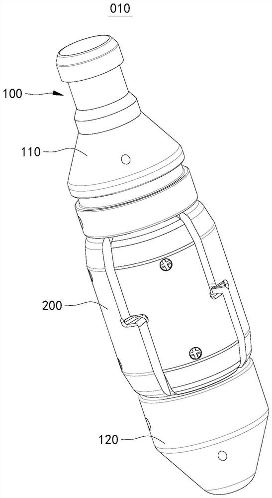
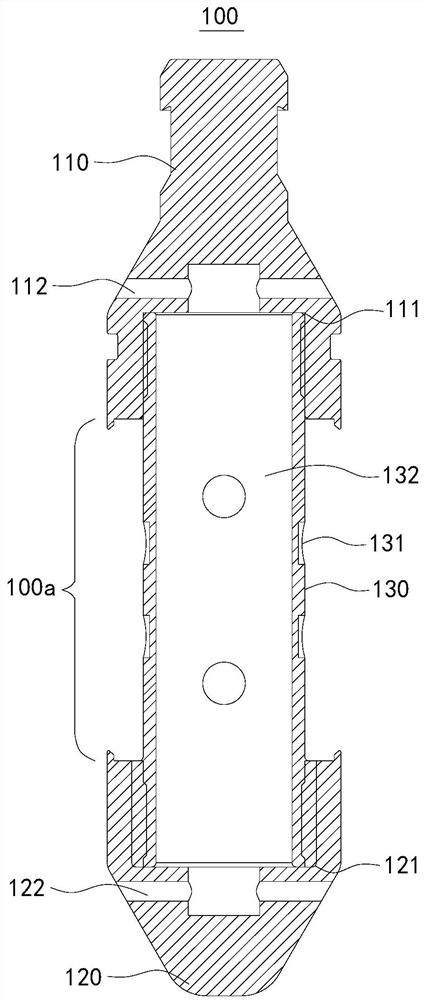
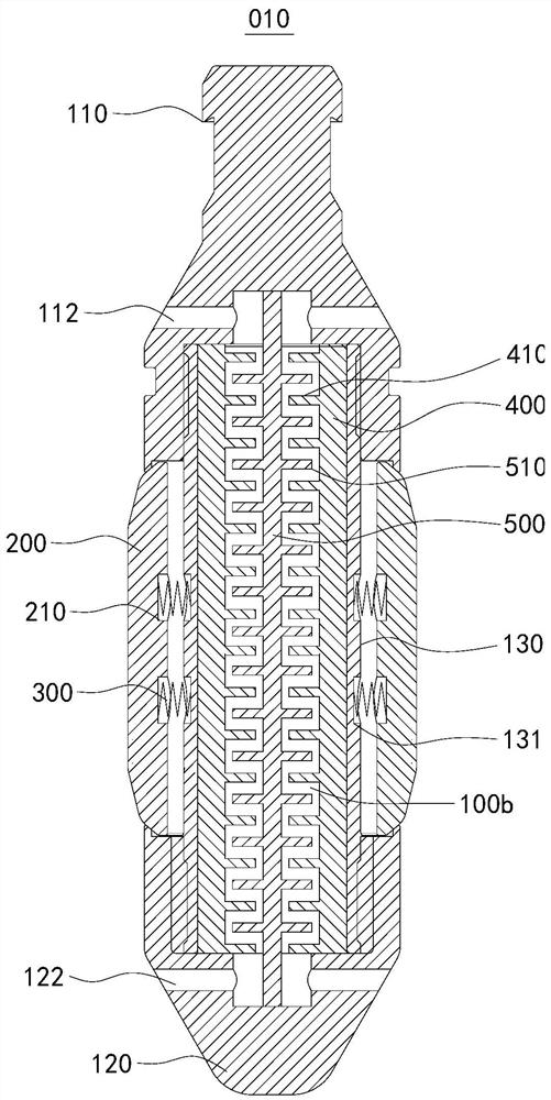
[0039] figure 1 A schematic diagram of the external structure of the plunger 010 provided in this embodiment. figure 2 A schematic structural diagram of the core body 100 in the plunger 010 provided in the embodiment of the present application. image 3 A schematic cross-sectional structure diagram of the plunger 010 provided in this embodiment. Please refer to figure 1 and figure 2, in this embodiment, the plunger 010 includes a core body 100 , a sealing gasket 200 , a first elastic reset member 300 , an outer restrictor tube 400 and an inner restrictor column 500 .

[0040] The core body 100 includes an upper end 110 , a lower end 120 and a core tube 130 . One end of the upper end 110 is provided with an upper connecting hole 111 , and an internal thread is arranged in the upper connecting hole 111 . An upper fluid hole 112 is defined on the side of the upper end 110 . The upper fluid hole 112 extends radially and communicates with the upper connecting hole 111 and th...

Embodiment 2

[0049] Figure 5 A schematic cross-sectional structure diagram of the plunger 010 provided in this embodiment. The plunger 010 provided in this embodiment is basically the same as that described in Embodiment 1, except that, in this embodiment, one of the inner restrictor column 500 and the outer restrictor tube 400 is fixedly arranged, and the other Axially movable setting.

[0050] Specifically, in this embodiment, the inner restrictor column 500 can be axially movable, and the outer restrictor tube 400 is fixedly arranged. The outer restrictor tube 400 is fixedly arranged in the manner described in Embodiment 1.

[0051] When the plunger 010 goes down in the shut-in state, if the fluid resistance is too large, it will push the inner restrictor column 500 to move axially, so that the inner restrictor ring 510 and the outer restrictor ring 410 are in contact, and the inner restrictor post 500 and the outer restrictor ring 410 are in contact. The tortuous flow channel 100b ...

Embodiment 3

[0055] Figure 6 A schematic cross-sectional structure diagram of the plunger 010 provided in this embodiment. The plunger 010 provided in this embodiment is basically the same as that described in Embodiment 1, except that, in this embodiment, one of the inner restrictor column 500 and the outer restrictor tube 400 is fixedly arranged, and the other Axially adjustable position setting.

[0056] Specifically, in this embodiment, the position of the inner restrictor column 500 can be adjusted axially, and the outer restrictor tube 400 is fixedly arranged. The outer restrictor tube 400 is fixedly arranged in the manner described in Embodiment 1.

[0057] The size of the gap between the inner restrictor ring 510 and the outer restrictor ring 410 can be adjusted freely by adjusting the axial position of the inner restrictor post 500 . The size of the gap between the inner restrictor ring 510 and the outer restrictor ring 410 is adjusted according to the energy condition at the ...


PUM


Abstract

The invention relates to the technical field of natural gas and oil exploitation, and discloses a plunger. The plunger comprises a core body, a sealing gasket, a first elastic reset piece, an outer flow limiting pipe and an inner flow limiting column; a fluid channel extending in the axial direction of the core body is arranged in the core body, the outer flow limiting pipe is arranged in the fluid channel, a plurality of outer flow limiting rings protruding inwards in the radial direction are arranged on the inner circumferential face of the outer flow limiting pipe, the plurality of outer flow limiting rings are arranged at intervals in the axial direction, and the inner flow limiting column is arranged in the outer flow limiting pipe; a plurality of inner flow limiting rings protruding outwards in the radial direction are arranged on the outer circumferential face of the inner flow limiting column and arranged at intervals in the axial direction; the inner flow limiting rings and the outer flow limiting rings are alternately arranged in the axial direction; the outer diameters of the inner flow limiting rings are larger than the inner diameters of the outer flow limiting rings; the outer diameters of the inner flow limiting rings are smaller than the inner diameter of the outer flow limiting pipe; and the distance between adjacent outer flow limiting rings is larger than the thickness of each inner flow limiting ring. The plunger can smoothly descend in a well shut-in state while ensuring the lifting efficiency.

Description

technical field [0001] The application relates to the technical field of natural gas and oil exploitation, and in particular to a plunger. Background technique [0002] During the development of natural gas or oil wells, in order to increase the production of natural gas or oil, it is necessary to lift the liquid at the bottom of the well to the surface. [0003] A plunger is provided in the related art. A plurality of sealing gaskets are arranged on the periphery of the core body of the plunger, and these sealing gaskets are in contact with the inner wall of the shaft under the action of the elastic member to form a seal. In the shut-in state, the plunger goes down to the bottom of the well. When the well is opened, the pressure generated by the fluid below the plunger drives the plunger upward, thereby lifting the effusion above the plunger upward, and discharging the effusion above the plunger through the wellhead. [0004] The problem with the above-mentioned plunger ...

Claims


Application Information

Patent Timeline
Patent Type & Authority Applications(China)
IPC IPC(8): F04B53/14F04B47/12
CPCF04B53/14F04B53/143F04B47/12
Inventor 刘书豪陈俊宏刘树飞苏诗策唐勇
Owner 成都百胜野牛科技有限公司
Why Eureka
Try Eureka