
Waste gas collecting and purifying treatment device for sintering furnace

A waste gas collection, purification and treatment technology, applied in waste heat treatment, charging treatment type, descaling device, etc., can solve the problems affecting the effect of pipeline exhaust, atmospheric environment pollution, pollution of sintering furnace, etc., to achieve convenient movement and installation, occupation Small size, strong overall effect

Active Publication Date: 2021-06-18
FUSHUN HANKING DRI CO LTD
View PDF17 Cites 0 Cited by
  • Summary
  • Abstract
  • Description
  • Claims
  • Application Information

AI Technical Summary

Problems solved by technology

[0003] The sintering furnace will produce a large amount of waste gas and suspended particles when processing various materials for sintering. In the prior art, the exhaust port of the sintering furnace is mostly connected with the outside world through pipes, which will pollute the atmospheric environment; and after long-term use of the pipes , a large amount of floating ash will adhere to the surface, which will affect the exhaust effect of the pipeline. At the same time, it may fall into the furnace and pollute the sintering furnace.

Method used


Image

  • Waste gas collecting and purifying treatment device for sintering furnace
  • Waste gas collecting and purifying treatment device for sintering furnace
  • Waste gas collecting and purifying treatment device for sintering furnace

Examples


Embodiment Construction

[0044]In order to make the purpose, technical solutions and advantages of the embodiments of the present invention clearer, the technical solutions in the embodiments of the present invention will be clearly and completely described below in conjunction with the accompanying drawings in the embodiments of the present invention. Obviously, the described embodiments It is a part of embodiments of the present invention, but not all embodiments. Based on the embodiments of the present invention, all other embodiments obtained by persons of ordinary skill in the art without making creative efforts belong to the protection scope of the present invention.

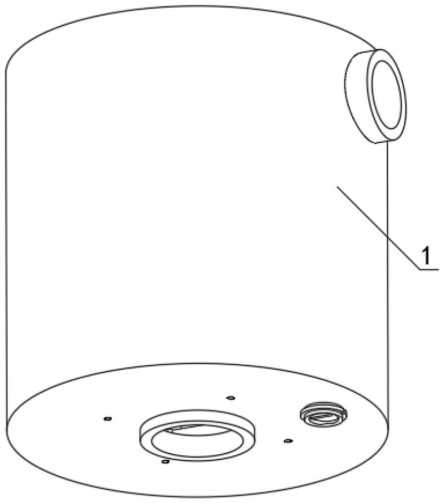
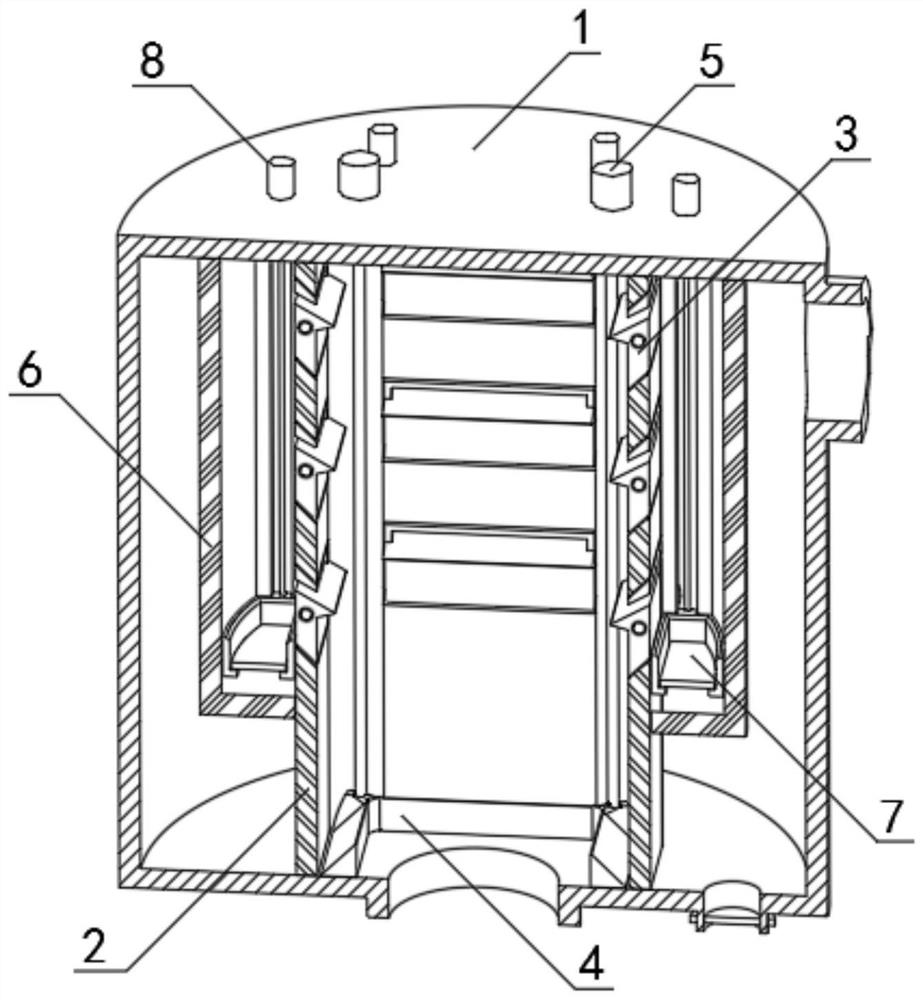
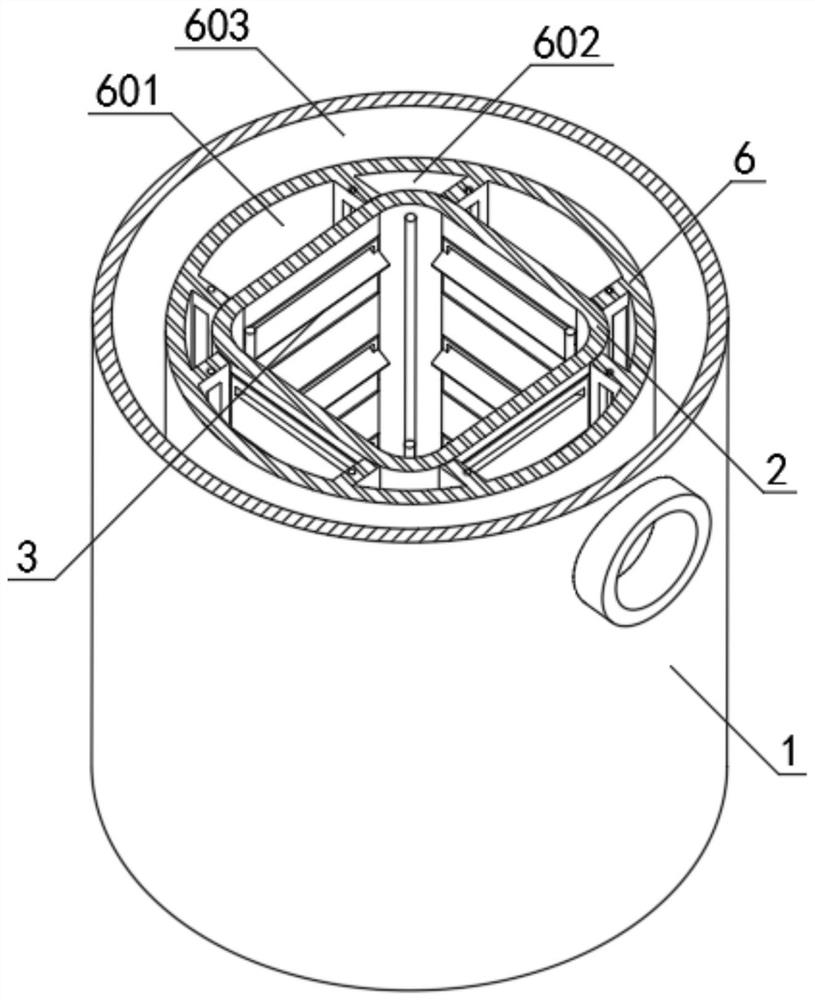
[0045] The embodiment of the present invention proposes a waste gas collection and purification treatment device for sintering furnace, which includes a treatment box 1, an inner pipe 2, a rotating part 3, a cleaning part 4, a first drive assembly 5, a barrier frame 6, a holding part 7 and a second drive assembly 8, exemplary, suc...


PUM


Abstract

The invention belongs to the field of environmental protection equipment, and particularly relates to a waste gas collecting and purifying treatment device for a sintering furnace. The device a treatment box, an inner pipe, a rotating piece, a sweeping piece, a first driving assembly, a blocking frame, a containing piece and a second driving assembly, wherein an air inlet is formed in the lower end of the treatment box, and an air outlet is formed in the upper end of the side wall of the treatment box; the inner pipe is vertically arranged in the treatment box, the upper end and the lower end of the inner pipe are fixedly connected with the inner top and the inner bottom of the treatment box respectively, and the inner pipe communicates with the air inlet of the treatment box; and the plurality of sets of rotating pieces are arranged on the inner pipe in a penetrating mode, and the sides, facing the central axis of the inner pipe, of the sets of rotating pieces protrude out of the inner wall of the inner pipe. The treatment box, the blocking frame and the inner pipe are sequentially sleeved and connected to form a main body of the waste gas treatment device and are matched with the treatment mechanism to form the complete waste gas treatment device, and the waste gas treatment device is small in occupied volume, high in integrity and convenient in movement and placement.

Description

technical field [0001] The invention belongs to the field of environmental protection equipment, in particular to a waste gas collection and purification treatment device for a sintering furnace. Background technique [0002] The sintering furnace is a kind of furnace in which the solid particles inside are bonded to each other at high temperature, the voids and grain boundaries gradually decrease, the total volume of the solid particles shrinks, the density increases, and finally becomes a kind of dense polycrystalline sintered body. Tool. [0003] The sintering furnace will produce a large amount of waste gas and suspended particles when processing various materials for sintering. In the prior art, the exhaust port of the sintering furnace is mostly connected with the outside world through pipes, which will pollute the atmospheric environment; and after long-term use of the pipes , a large amount of floating ash will adhere to the surface, which will affect the exhaust ef...

Claims


Application Information

Patent Timeline
IPC IPC(8): F27D17/00F27D25/00B01D53/18B01D53/78
CPCF27D17/008F27D17/004F27D25/00B01D53/18B01D53/78F27D2017/007F27M2003/04
Inventor 郑员锋陈光
Owner FUSHUN HANKING DRI CO LTD
Learn More