Intelligent trolley of autonomous navigation robot control system based on ROS
A control system and smart car technology, applied in control/regulation systems, two-dimensional position/channel control, motor vehicles, etc., can solve the problems of poor navigation and positioning, backward path planning algorithms, and inability to calculate paths, etc. problem, to achieve the effect of enhancing motion ability and robustness, low cost, and sensitive speed control
- Summary
- Abstract
- Description
- Claims
- Application Information
AI Technical Summary
Problems solved by technology
Method used
Image
Examples
Embodiment 1
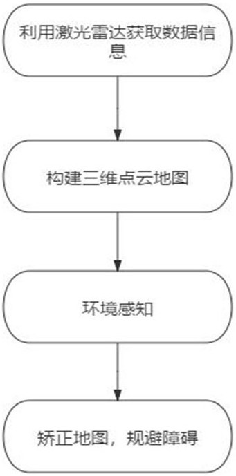
[0043] refer to Figure 1~Figure 16 , is the first embodiment of the present invention, provides a kind of intelligent car of the autonomous navigation robot control system based on ROS, comprises:
[0044] S1: The car is equipped with a laser radar, a camera and a gravity acceleration sensor, and the laser radar is used to obtain the current position, distance information and environmental information of the car itself.
[0045] S2: Create a grid map based on the robot operating system, and use the SLAM algorithm and depth camera vision fusion to construct a 3D point cloud map.
[0046] S3: The car uses the robot operating system to sense the distance information and the visual odometer of the RGB-D depth camera to generate a three-dimensional point cloud map.
[0047] S4: The robot operating system corrects the three-dimensional point cloud map according to the GPS when the path forms a loop, and calculates the path of the car to avoid obstacles.
[0048] refer to figure...
Embodiment 2
[0091] refer to Figure 17~Figure 19 , which is the second embodiment of the present invention. This embodiment is different from the first embodiment in that it provides a hardware module of a smart car of a ROS-based autonomous navigation robot control system, which specifically includes:
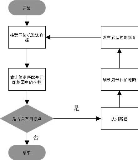
[0092] refer to Figure 17 , using STM32F103 as the main controller to output the PWM for controlling the motor and the motor, read the encoder and IMU (inertial measurement unit) data at the same time, and send it to the upper computer Jeston nano through the serial port, and the Jeston nano performs the main calculation, in the drawing mode Next, the map is constructed by obtaining the data of the lidar and the depth camera. In the navigation mode, the lidar and the depth camera are used to match the feature points to estimate the robot's own pose, calculate the motion path, and send the control expectation to the lower computer STM32.
[0093] refer to Figure 18 , 12V power input, L...
PUM
 Abstract
Description
Claims
Application Information
 - R&D
- Intellectual Property
- Life Sciences
- Materials
- Tech Scout
- Unparalleled Data Quality
- Higher Quality Content
- 60% Fewer Hallucinations
Browse by: Latest US Patents, China's latest patents, Technical Efficacy Thesaurus, Application Domain, Technology Topic, Popular Technical Reports.
© 2025 PatSnap. All rights reserved.Legal|Privacy policy|Modern Slavery Act Transparency Statement|Sitemap|About US| Contact US: help@patsnap.com


