High-gain patch antenna with reconfigurable directional diagram

A patch antenna and high-gain technology, applied in the field of communication, can solve the problems of large antenna gain difference, difficulty in application, and low antenna gain

Active Publication Date: 2021-06-18
深圳市宏胜实业有限公司
View PDF4 Cites 3 Cited by
  • Summary
  • Abstract
  • Description
  • Claims
  • Application Information

AI Technical Summary

Problems solved by technology

However, the above two types of pattern reconfigurable antennas all face a common defect, that is, the antenna gain is low, and the antenna gain difference between the two states is large, especially when some antenna systems

Method used


Image

  • High-gain patch antenna with reconfigurable directional diagram
  • High-gain patch antenna with reconfigurable directional diagram
  • High-gain patch antenna with reconfigurable directional diagram

Examples


Embodiment 1

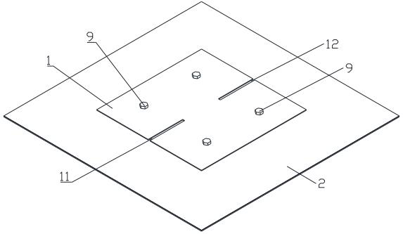
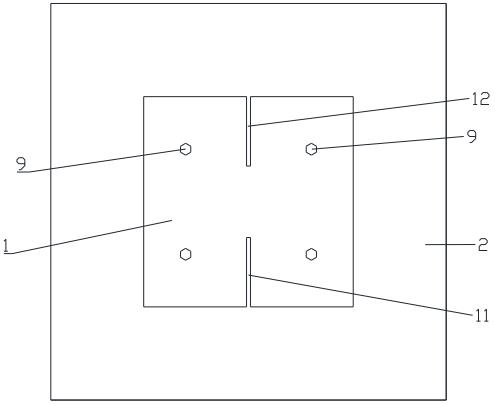
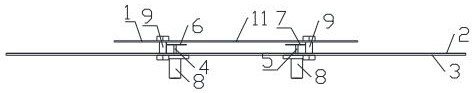
[0030] see Figure 1 to Figure 5 , a high-gain patch antenna with a reconfigurable pattern, including a sequentially stacked metal floor 2, a first dielectric layer, a metal sheet layer, a second dielectric layer, and a layer for forming a TM20 Die and TM 21 The radiation patch 1 of the mold; also includes a first probe 4 and a second probe 5; the metal sheet layer is provided with a first metal sheet 6 and a second metal sheet 7; the first probe 4 is directed to the The first metal sheet 6 feeds power, and the second probe 5 feeds power to the second metal sheet 7; both the first metal sheet 6 and the second metal sheet 7 are coupled to the radiation patch 1 ; The position of the same straight line of the radiation patch 1 is provided with a first slit 11 and a second slit 12, and the length directions of the first slit 11 and the second slit 12 are all in line with TM 20 The direction of the current vector of the mode is parallel; the first metal sheet 6 and the second meta...

Embodiment 2

[0033] On the basis of the structure of the above embodiment, the straight line passes through the center of the radiation patch 1 and is the central axis of the first slit 11 and the second slit 12; the distance between the first slit 11 and the second slit 12 The end of the second slot 12 extends to the edge of the radiation patch 1, and the end of the second slot 12 away from the first slot 11 also extends to the edge of the radiation patch 1, so that the performance of the antenna is better.

Embodiment 3

[0035] On the basis of the structure of the above embodiment, the straight line is parallel to the long side of the radiation patch 1; the central operating frequency of the antenna is λ; the long side of the radiation patch 1 is A, and the wide side is B; the The length of the first slit 11 is equal to the length of the second slit 12, both are C; the width of the first slit 11 is also equal to the width of the second slit 12, both are D, wherein, 0.5λ≤ A≤λ, 0.5λ≤B≤λ, 0.1λ≤C<0.5λ, 0


PUM


Abstract

The invention provides a high-gain patch antenna with a reconfigurable directional diagram. The high-gain patch antenna comprises a metal floor, a first dielectric layer, a metal sheet layer, a second dielectric layer and a radiation patch which are sequentially stacked, wherein the radiation patch is used for forming a TM20 mode and a TM21 mode; the antenna further comprises a first probe and a second probe; the metal sheet layer is provided with a first metal sheet and a second metal sheet; the first probe feeds power to the first metal sheet, and the second probe feeds power to the second metal sheet; the first metal sheet and the second metal sheet are coupled with the radiation patch; a first gap and a second gap are formed in the same straight line of the radiation patch, and the length directions of the first gap and the second gap are parallel to the current vector direction of the TM20 mode; the first metal sheet and the second metal sheet are in mirror symmetry about a plane, and the plane passes through the straight line and is perpendicular to the radiation patch; a common-mode signal or a differential-mode signal is fed into the first probe and the second probe; and through mutual switching between the common-mode signal and the differential-mode signal, antenna dual-beam and edge emission direction pattern reconstruction is realized.

Description

technical field [0001] The invention relates to the technical field of communication, in particular to a high-gain patch antenna with a reconfigurable pattern. Background technique [0002] With the rapid development of modern wireless communication, antennas with reconfigurable pattern are widely used in wireless communication in various special scenarios to effectively improve the channel capacity and communication quality of the communication system. [0003] In recent years, a large number of researchers at home and abroad have done a lot of research on pattern reconfigurable antennas. The literature "K.L. Wong, et al., Reconfigurable square-ring patch antenna with pattern diversity, IEEE Trans. Antennas Propag., vol. 55, no. 2, pp. 472–475, Feb.2007." A single-feed rectangular patch antenna with a square ring. One pair of sides of the square ring is directly shorted to the metal floor, and the other pair of sides is connected to a p-i-n diode and then shorted to the me...

Claims


Application Information

Patent Timeline
IPC IPC(8): H01Q1/38H01Q1/50H01Q1/36H01Q1/48
CPCH01Q1/36H01Q1/38H01Q1/48H01Q1/50
Inventor 张晓洪凯东袁涛
Owner 深圳市宏胜实业有限公司
Why Eureka
Try Eureka