
Distributed low-voltage direct-current power supply network topology structure

A power supply network, low-voltage direct current technology, applied in the field of distributed low-voltage direct current power supply network topology, can solve the problems that cannot be included in the overall planning of the energy storage station, equipment utilization rate reduction, limitations, etc., to simplify the power supply equipment and energy storage in the station equipment, improving efficiency and improving reliability

Inactive Publication Date: 2021-06-18
NR ELECTRIC CO LTD +1
View PDF0 Cites 0 Cited by
  • Summary
  • Abstract
  • Description
  • Claims
  • Application Information

AI Technical Summary

Problems solved by technology

[0005] (1) The power consumption of a single micro-module in the data center is relatively large, and the power supply voltage of DC 240 is used. Due to the limited capacity, it is also necessary to build multiple centralized power supply modules of the same scale to meet the power demand of the data center.
[0006] (2) The DC bus needs to independently allocate energy storage units to the power supply system, which cannot be included in the overall planning of the energy storage station. Compared with the traditional UPS method, only the original lead-acid battery is replaced with the same lithium battery as the energy storage station. , did not achieve the goal of integrating the energy storage station with the data center UPS
[0007] (3) The centralized solution also needs to be separately configured for large-capacity substation transformers in the data center, which cannot be reasonably matched with the modular construction of the IT equipment micro-modules in the data center, which will inevitably lead to an expansion of investment and a reduction in the utilization rate of equipment

Method used


Image

  • Distributed low-voltage direct-current power supply network topology structure
  • Distributed low-voltage direct-current power supply network topology structure
  • Distributed low-voltage direct-current power supply network topology structure

Examples


Embodiment Construction

[0052]In order to make the object, technical solution and advantages of the present invention more clear, the present invention will be further described in detail below in conjunction with the examples. It should be understood that the specific embodiments described here are only used to explain the present invention, and are not intended to limit the protection scope of the present invention.

[0053] The application principle of the present invention will be described in detail below in conjunction with the accompanying drawings.

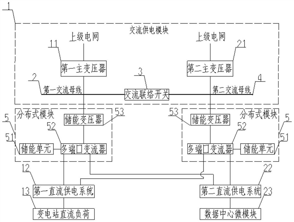
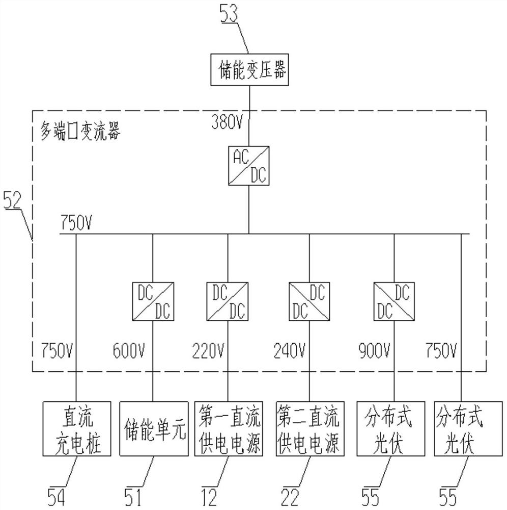
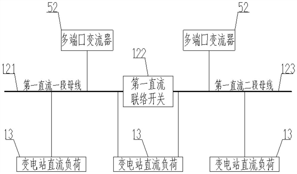
[0054] The present invention provides a distributed low-voltage DC power supply network topology structure, with distributed modules as the core, and multiple distributed low-voltage DC power supply networks in smart energy stations are formed through AC-DC conversion, which are used for DC loads in substations and micro-modules in data centers According to regionalization, modularization and distributed DC power supply.

[0055] Such as figure...


PUM


Abstract

The invention discloses a distributed low-voltage direct-current power supply network topology structure, which comprises an alternating-current power supply module, a plurality of first direct-current power supply systems, a plurality of second direct-current power supply systems and a plurality of distributed modules, and is characterized in that the alternating-current power supply module comprises a first alternating-current power supply unit and a second alternating-current power supply unit; the first alternating-current power supply unit and the second alternating-current power supply unit are connected through an alternating-current interconnection switch; and the first end of each distributed module is connected with the first alternating-current power supply unit or the second alternating-current power supply unit, the second end is connected with the first direct-current power supply system, and the third end is connected with the second direct-current power supply system. The alternating-current power supply module, the distributed modules and the direct-current power supply systems all adopt power redundancy and network structure mutual backup, so that the reliability of DC power supply of the transformer substation and DC power supply of the data center is improved.

Description

technical field [0001] The invention relates to the field of DC power supply systems in smart energy substations, in particular to a distributed low-voltage DC power supply network topology. Background technique [0002] The State Grid Corporation of China is currently focusing on the construction of the ubiquitous power Internet of Things. Substations are the core resources of power grid enterprises and play an important pivotal role in undertaking power transmission and distribution and regional power supply. Relying on widely distributed substations, the construction of smart energy stations integrating various functional modules such as substations, energy storage stations, data center stations, photovoltaic stations, and charging stations is a key component of the ubiquitous power Internet of Things. [0003] While integrating energy storage stations, data center stations, photovoltaic stations and charging stations, smart energy stations face the technical problem of h...

Claims


Application Information

Patent Timeline
Patent Type & Authority Applications(China)
IPC IPC(8): H02J3/36H02J1/10H02J3/32
CPCH02J1/10H02J3/32H02J3/36Y02E60/60
Inventor 金忠德吴俊魏旭东刘宇
Owner NR ELECTRIC CO LTD
Learn More