MEMS sensor and electronic device

A sensor and sensitive technology, applied in the field of measurement, can solve the problems of complex circuit design, high cost, and many process steps, and achieve the effect of improving detection sensitivity, easy implementation, and simple annealing process

Active Publication Date: 2021-06-18
WEIFANG GOERTEK MICROELECTRONICS CO LTD
View PDF10 Cites 1 Cited by
  • Summary
  • Abstract
  • Description
  • Claims
  • Application Information

AI Technical Summary

Problems solved by technology

This kind of MEMS microphone design requires sputtering a permanent magnet film on the diaphragm. When the diaphragm vibrates, it will drive the permanent magnet film unit to move up and down, which will cause changes in the magnetic field strength and direction at the position of the magnetoresistive unit. However, this permanent Thin film sputtering of magnets is expensive
At present, similar sensors are using magnetoresistive units to form a differential Wheatstone full-bridge circuit. It is necessary to adjust the positive and negative directions of the current applied in the adjacent wires of each magnetoresistance unit to achieve the purpose of differential. The circuit design is relatively complicated and the process steps relatively more

Method used


Image

  • MEMS sensor and electronic device
  • MEMS sensor and electronic device
  • MEMS sensor and electronic device

Examples


Embodiment Construction

[0026] The following will clearly and completely describe the technical solutions in the embodiments of the present invention with reference to the accompanying drawings in the embodiments of the present invention. Obviously, the described embodiments are only part of the embodiments of the present invention, not all of them. Based on the embodiments of the present invention, all other embodiments obtained by persons of ordinary skill in the art without creative efforts fall within the protection scope of the present invention.

[0027] It should be noted that if there is a directional indication (such as up, down, left, right, front, back...) in the embodiment of the present invention, the directional indication is only used to explain the position in a certain posture (as shown in the accompanying drawing). If the specific posture changes, the directional indication will also change accordingly.

[0028] In addition, if there are descriptions involving "first", "second" and ...


PUM


Abstract

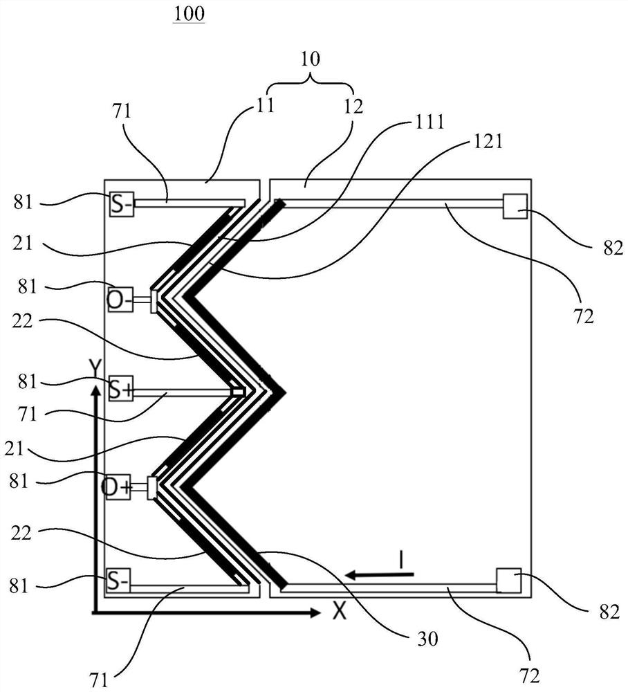
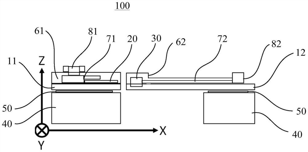
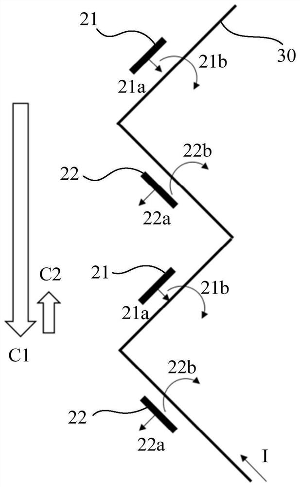
The invention discloses an MEMS sensor and electronic equipment, and the MEMS sensor comprises: a vibrating diaphragm layer which comprises a fixed part and a sensitive part which can vibrate relative to the fixed part; a detection piece which comprises a first magnetic resistance unit and a second magnetic resistance unit which are connected in sequence, an included angle is formed between the long axis direction of the first magnetic resistance unit and the long axis direction of the second magnetic resistance unit, and the included angle is smaller than 180 degrees; a wire, of which the extension direction is parallel to the arrangement direction of the first magnetic resistance unit and the second magnetic resistance unit; wherein the detection piece and the wire are respectively fixed on the fixed part and the sensitive part, the magnetization direction of the reference layer of the first magnetic resistance unit is vertical to the long axis direction of the first magnetic resistance unit and faces the wire, and the magnetization direction of the reference layer of the second magnetic resistance unit is vertical to the long axis direction of the second magnetic resistance unit and is back to the wire. According to the technical scheme, the production cost and the circuit design complexity can be reduced, implementation and manufacturing are easy, and the detection sensitivity can be improved.

Description

technical field [0001] The invention relates to the technical field of measurement, in particular to a MEMS sensor and electronic equipment. Background technique [0002] At present, mainstream microphones, pressure sensors and displacement sensors are mostly detected by the principle of flat capacitors, that is, the back plate and the diaphragm are formed on the basis of the substrate, and there is a gap between the back plate and the diaphragm, so that the back A capacitive detection structure is formed between the pole plate and the diaphragm. Taking condenser microphones as an example, the design needs to include a larger back cavity to increase the mechanical sensitivity of the diaphragm. If the volume of the rear cavity is too small, it is not conducive to air circulation, which will greatly reduce the mechanical sensitivity of the diaphragm. On the other hand, for pressure equalization, dense perforations are usually designed on the back plate, and the gap caused by...

Claims


Application Information

Patent Timeline
Patent Type & Authority Applications(China)
IPC IPC(8): H04R19/04H04R31/00
CPCH04R19/04H04R31/00H04R2201/003
Inventor 周汪洋邹泉波冷群文安琪赵海轮丁凯文周良
Owner WEIFANG GOERTEK MICROELECTRONICS CO LTD
Why Eureka
Try Eureka