Conductive sputter targets with silicon, zirconium and oxygen

A sputtering and resistivity technology, which is applied in sputtering coating, circuit, zirconia, etc., can solve the problems of affecting the sputtering rate along the target tube, affecting the uniformity of plasma density, and expensive radio frequency sputtering equipment. Effects of reduced arcing, lower resistivity, and higher conductivity

Pending Publication Date: 2021-06-18
SOLERAS ADVANCED COATINGS NV
View PDF7 Cites 0 Cited by
  • Summary
  • Abstract
  • Description
  • Claims
  • Application Information

AI Technical Summary

Problems solved by technology

In the case of a rotating cylindrical magnetron, the power delivery is further restricted to the position corresponding to the end of the target tube, which can seriously affect the uniformity of the plasma density and thus the sputtering rate along the target tube
Also, RF sputtering equipment is much more expensive to achieve similar sputtering rates than DC or AC sputtering

Method used

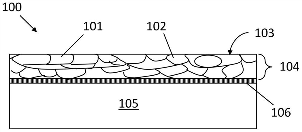
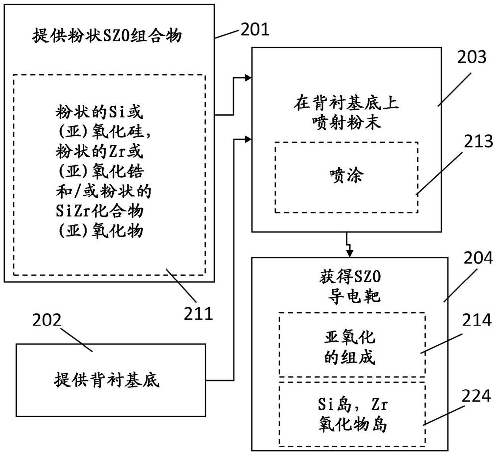

Image

  • Conductive sputter targets with silicon, zirconium and oxygen
  • Conductive sputter targets with silicon, zirconium and oxygen
  • Conductive sputter targets with silicon, zirconium and oxygen

Examples


Embodiment Construction

[0040] The present invention will be described with respect to particular embodiments and with reference to certain drawings but the invention is not limited thereto but only by the claims. The dimensions and relative dimensions do not correspond to actual reductions for practicing the invention.

[0041] In the description and claims, the terms first, second, etc. are used to distinguish similar elements and not necessarily to describe an order in time, space, hierarchy or any other manner. It is to be understood that the terms so used are interchangeable under appropriate circumstances and that the embodiments of the invention described herein are capable of operation in other sequences than described or illustrated herein.

[0042] Furthermore, the terms top, bottom, etc. in the description and claims are used for descriptive purposes and not necessarily for describing relative positions. It is to be understood that the terms so used are interchangeable under appropriate c...


PUM

PropertyMeasurementUnit
thicknessaaaaaaaaaa
sizeaaaaaaaaaa
sizeaaaaaaaaaa

Abstract

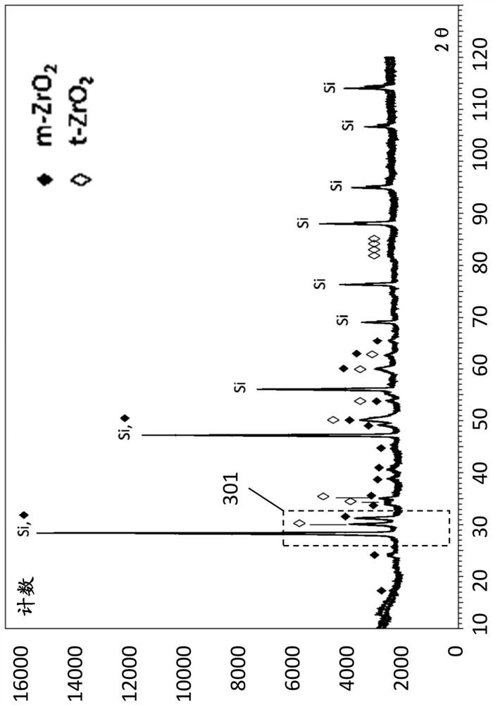
A target for sputtering comprises SiZrxOy wherein x is higher than 0.02 but not higher than 5, and y is higher than 0.03 but not higher than 2*(1+x), wherein the target has anXRD pattern with silicon 2-theta peak at 28.29 degree + / - 0.3 degree, or a tetragonal phase ZrO2 2-theta peak at 30.05 degree + / - 0.3 degree.The target has a low resistivity, below 1000 ohm.cm, preferably below 100 ohm.cm, more preferably below 10 ohm.cm, even lower than 1 ohm.cm.

Description

technical field [0001] The present invention relates to the field of silicon oxide zirconium sputtering targets. More particularly, the present invention relates to electrically conductive silica zirconia sputtering targets, and to methods of making such targets. Background technique [0002] Many applications (eg surface protection, optics, tribology, etc.) require the presence of one or more layers of material covering the substrate, which impart specific and predetermined properties to the surface of the substrate. A typical technique suitable for many types of materials and specific applications is to deposit the material by sputtering. [0003] The technique of material deposition by means of sputtering has been known for decades. Typically, the plasma is generated in a low-pressure chamber in which an inert gas such as argon or a reactive gas such as oxygen or nitrogen is present and is deposited on a so-called "sputter target" containing the material) and the "subs...

Claims


Application Information

Patent Timeline
Patent Type & Authority Applications(China)
IPC IPC(8): C23C14/34C23C14/08C23C4/10C23C4/04C23C4/18
CPCH01J37/3426C23C4/06C23C4/11C23C4/18C23C14/3414C23C14/08C23C14/0676C04B35/481C04B2235/765C04B2235/78C04B2235/96C23C14/0036C01G25/02C01P2002/72C01P2006/40
Inventor I·卡雷蒂吉安加斯普罗W·C·S·德博斯谢尔D·K·德布鲁恩G·国彬F·法克H·埃利亚诺
Owner SOLERAS ADVANCED COATINGS NV
Why Eureka
Try Eureka