Heat energy recovery device of customized tail gas system

A heat recovery and tail gas technology, applied in lighting and heating equipment, chemical instruments and methods, combustion product treatment, etc., can solve problems such as energy loss, heat waste, environmental pollution, etc., and achieve fast settlement and long settlement time Effect

Inactive Publication Date: 2021-06-22
江苏天蓝智能装备有限公司
View PDF4 Cites 0 Cited by
  • Summary
  • Abstract
  • Description
  • Claims
  • Application Information

AI Technical Summary

Problems solved by technology

[0002] At present, in the industrial production that needs to incinerate fuel, usually, the fuel is directly burned to generate heat energy, and then the heat energy of combustion is used, but after actual production, it is found that although the heat energy of combustion accounts for the absolute Most of it, but some energy is lost, such as the exhaust gas of combustion. The exhaust gas produced by general combustion also has a relatively high temperature. dust, etc., causing environmental pollution

Method used


Image

  • Heat energy recovery device of customized tail gas system
  • Heat energy recovery device of customized tail gas system

Examples


Embodiment Construction

[0022] The present invention will be described in further detail below in conjunction with the accompanying drawings.

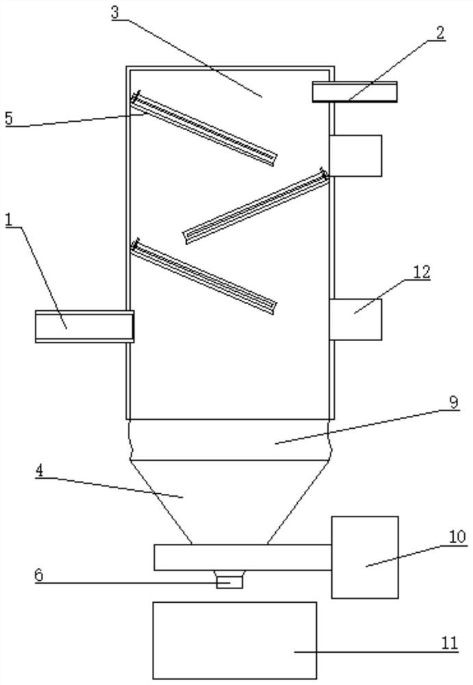
[0023] Such as figure 1 and 2 As shown, the present invention provides a heat recovery device for a customized tail gas system, including a tail gas settling mechanism, and the tail gas settling mechanism includes an inlet pipe 1, an outlet pipe 2, and a square settling tank 3;

[0024] The square settling tank 3 includes a correspondingly connected tank top plate, a tank front plate, a tank rear plate, two tank side plates and a tank bottom bucket 4;

[0025] The middle part of one tank side plate is provided with an air inlet hole, and the top of the other tank side plate is provided with an air outlet hole, the air inlet pipe 1 is connected to the outside of the air inlet hole, and the air outlet pipe 2 is connected to the air outlet hole;

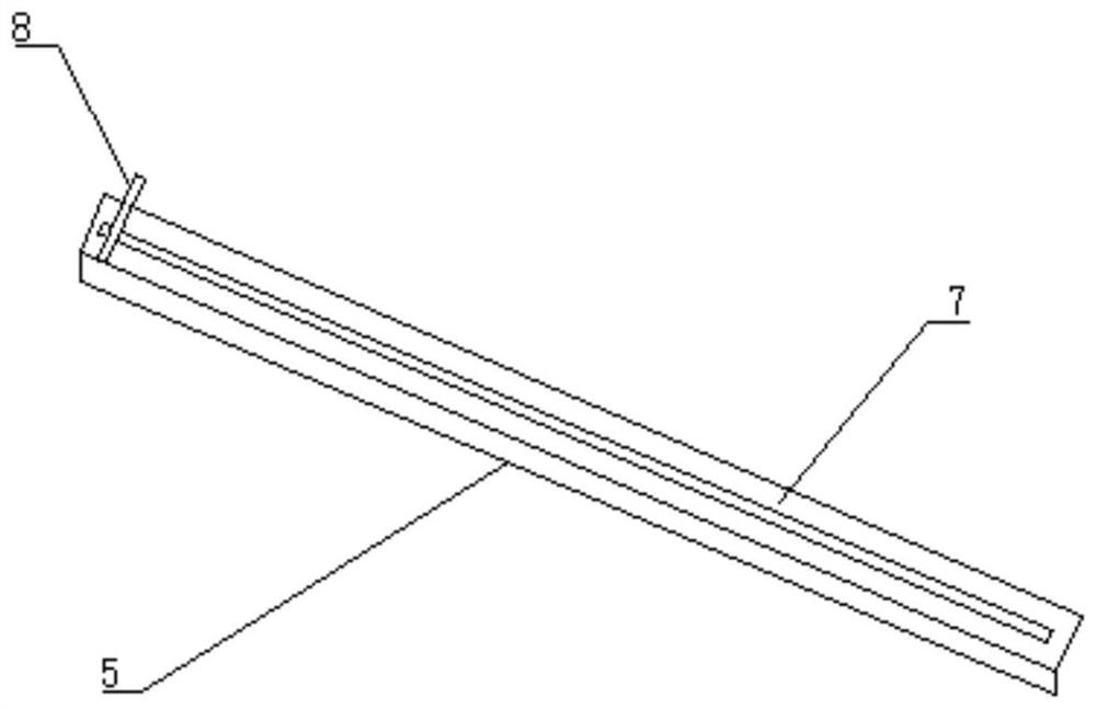
[0026] Several inclined baffles 5 are arranged in the square settling tank 3, and the two sides of the inclined ba...


PUM


Abstract

The invention relates to the field of tail gas regeneration, and discloses a heat energy recovery device of a customized tail gas system.The heat energy recovery device is characterized by comprising a tail gas settling mechanism, and the tail gas settling mechanism comprises a gas inlet pipeline, a gas outlet pipeline and a square settling tank; the square settling tank comprises a tank top plate, a tank front plate, a tank rear plate, two tank side plates and a tank bottom hopper which are correspondingly connected; a gas inlet hole is formed in the middle of one tank side plate, a gas outlet hole is formed in the top of the other tank side plate, the gas inlet pipeline is correspondingly communicated and connected with the outer side of the gas inlet hole, and the gas outlet pipeline is correspondingly communicated and connected with the gas outlet hole; a plurality of inclined baffles are arranged in the square settling tank, the two sides of each inclined baffle are fixedly connected with the tank front plate and the tank rear plate respectively, and the two ends of the top ends of every two adjacent inclined baffles are fixed to the inner sides of the two tank side plates respectively; the tank bottom hopper is in a funnel shape, and an ash discharging opening is formed in the bottom end of the tank bottom hopper.

Description

technical field [0001] The invention relates to the field of tail gas regeneration, more specifically, it relates to a heat recovery device for a customized tail gas system. Background technique [0002] At present, in the industrial production that needs to incinerate fuel, usually, the fuel is directly burned to generate heat energy, and then the heat energy of combustion is used, but after actual production, it is found that although the heat energy of combustion accounts for the absolute Most of it, but some energy is lost, such as the exhaust gas of combustion. The exhaust gas produced by general combustion also has a relatively high temperature. Dust and other things, causing environmental pollution. Contents of the invention [0003] The purpose of the present invention is to provide a heat energy recovery device for a customized tail gas system, through the multi-layer sedimentation of the fly ash, the fly ash in the tail gas is greatly reduced, so that the next s...

Claims


Application Information

Patent Timeline
IPC IPC(8): B01D45/02B01D45/06F23J3/00
CPCB01D45/02B01D45/06F23J3/00
Inventor 秦建张维浩陈秋远石宝山
Owner 江苏天蓝智能装备有限公司
Why Eureka
Try Eureka