Multipurpose integrated hydraulic function valve group

A functional valve and integrated technology, which is applied in the direction of fluid pressure actuation system components, servo motor components, fluid pressure actuation devices, etc., can solve the problems of many hidden dangers of hydraulic control system failures, scattered installation arrangements, and many hydraulic pipelines. , to achieve the effect of easy elimination of many hidden troubles, ingenious design and reasonable structure

Active Publication Date: 2021-06-22
山西煤矿机械制造股份有限公司
View PDF8 Cites 0 Cited by
  • Summary
  • Abstract
  • Description
  • Claims
  • Application Information

AI Technical Summary

Problems solved by technology

[0003] In the traditional method, the retractable tail, the hydraulic chain tightening system and the lubricating device are all realized by the hydraulic control system installed in different positions, and the cooling system is controlled by the electric ball valve, and the above mentioned four The hydraulic control system is scattered in installation and layout, resulting in many and miscellaneous liquid inlet and return pipelines and control pipelines, and the site layout is chaotic
In the working environment of coal mines, there are many and miscellaneous hydraulic pipelines, which will lead to many hidden troubles in the hydraulic control system, and there is a certain difficulty in troubleshooting

Method used


Image

  • Multipurpose integrated hydraulic function valve group
  • Multipurpose integrated hydraulic function valve group
  • Multipurpose integrated hydraulic function valve group

Examples


Embodiment Construction

[0033] The following clearly and completely describes the technical solutions in the embodiments of the present invention. Obviously, the described embodiments are only some of the embodiments of the present invention, but not all of them. Based on the embodiments of the present invention, all other embodiments obtained by persons of ordinary skill in the art without making creative efforts belong to the protection scope of the present invention.

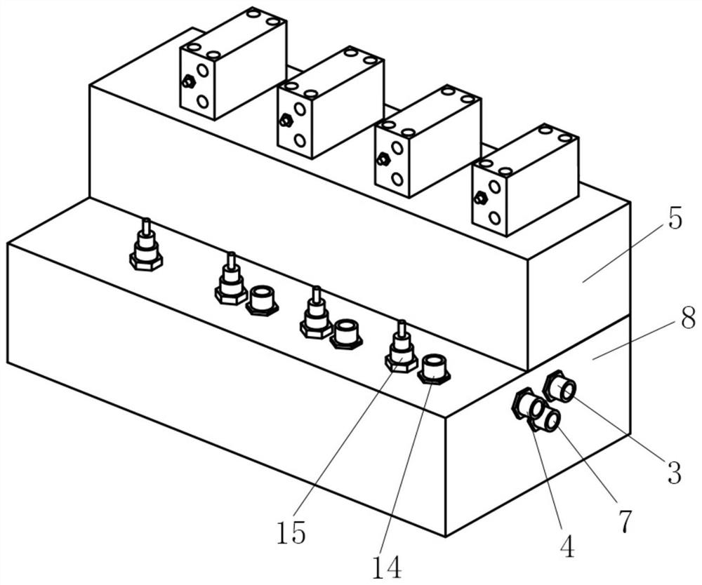
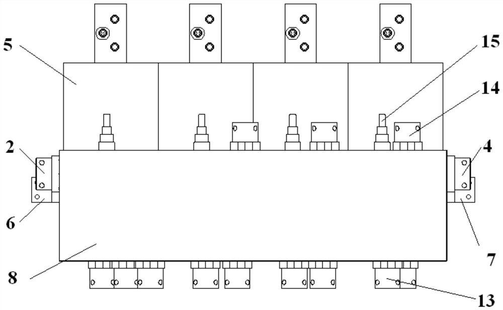
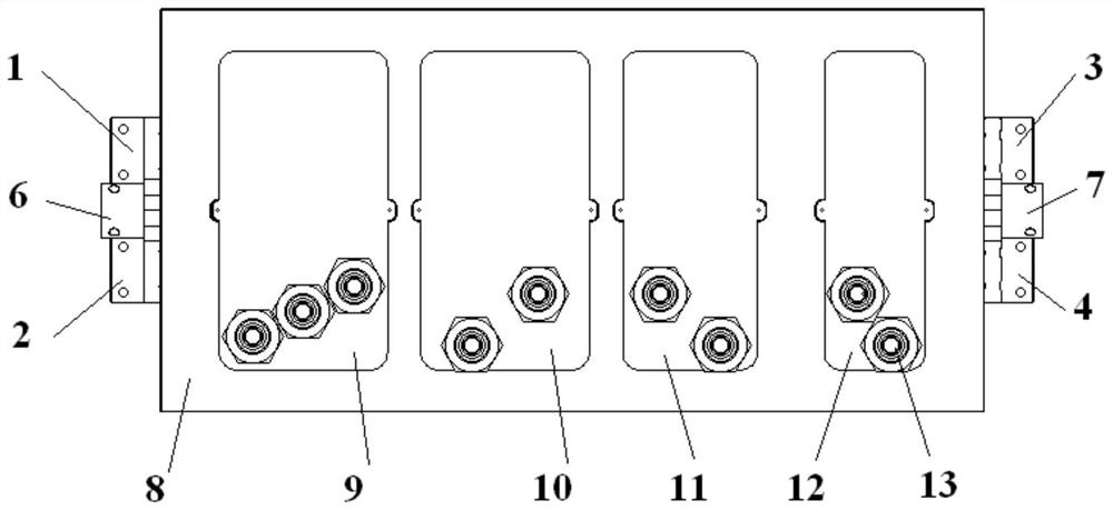
[0034] see Figure 1 to Figure 9 , the present invention provides a multi-purpose integrated hydraulic function valve group, including a main valve fluid distribution block 8, an embedded tightening chain motor function valve block 9, an embedded retractable tail function valve block 10, an embedded lubricating The functional valve block 11 of the device and the functional valve block 12 of the embedded cooling water system, each functional valve block is embedded in the main valve liquid distribution block 8 from left to right in a...


PUM


Abstract

The invention relates to the technical field of hydraulic systems of coal mine fully mechanized coal mining face transportation equipment, in particular to a multipurpose integrated hydraulic function valve group. The multipurpose integrated hydraulic function valve group comprises a main valve liquid distribution block, an embedded chain tightening motor function valve block, an embedded telescopic tail function valve block, an embedded lubricating device function valve block and an embedded cooling water system function valve block, the embedded chain tightening motor function valve block, the embedded telescopic tail function valve block, the embedded lubricating device function valve block and the embedded cooling water system function valve block are sequentially embedded into the main valve liquid distribution block from left to right in an embedded mode, a high-pressure liquid inlet, a high-pressure liquid return opening and a high-pressure liquid drainage opening are formed in the left side of the main valve liquid distribution block, a cooling water liquid inlet, a cooling water liquid return opening and a cooling water drainage opening are formed in the right side of the main valve liquid distribution block, four sets of electromagnetic pilot valves with the end faces connected are arranged on the upper surface of the main valve liquid distribution block so as to drive the corresponding function valve blocks to execute actions, and a corresponding connecting pipeline is arranged in the main valve liquid distribution block. The valve group is ingenious in design and reasonable in structure, and can effectively solve the problem that the number of hydraulic pipelines is large and the hydraulic pipelines are miscellaneous in the working environment of an underground coal mine.

Description

technical field [0001] The invention relates to the technical field of the hydraulic system of the transport equipment of the coal mine fully mechanized mining face, in particular to a multi-purpose integrated hydraulic function valve group. Background technique [0002] Scraper conveyor is one of the main equipment in fully mechanized mining face. Usually, the scraper conveyor realizes tightening the chain when starting up and loosening the chain when stopping through the action of the telescopic tail, so as to ensure the normal meshing or disengagement of the scraper chain and the sprocket, and to protect the chain; the lubrication device plays a role in protecting the chain. Lubrication of bearing components; during the working process, the cooling system of the conveying equipment can effectively reduce the temperature of the motor and reducer to ensure the reliable and safe operation of the transmission device; during the chain cutting and connecting process, the convey...

Claims


Application Information

Patent Timeline
Patent Type & Authority Applications(China)
IPC IPC(8): F15B13/02F15B21/0423F15B19/00
CPCF15B13/021F15B21/0423F15B19/00
Inventor 任锡义靳宇晖于平赵丽霞卫贤涛刘帅
Owner 山西煤矿机械制造股份有限公司
Why Eureka
Try Eureka