Rotary kiln catch wheel hydraulic system and working method thereof

A hydraulic system and rotary kiln technology, applied in the field of rotary kiln, can solve problems such as shortening the service life of equipment and equipment damage, and achieve the effects of saving flow adjustment time, facilitating operation, and ensuring safety

Pending Publication Date: 2021-06-22
ACRE COKING & REFRACTORY ENG CONSULTING CORP DALIAN MCC
View PDF0 Cites 2 Cited by
  • Summary
  • Abstract
  • Description
  • Claims
  • Application Information

AI Technical Summary

Problems solved by technology

After this force is superimposed with the downward channeling force of the rotary kiln itself, it may produce the maximum force beyond the surface of the retaining wheel and the bearing of the retaining wheel, thus causing damage to the equipment or greatly shortening the service life of the equipment

Method used


Image

  • Rotary kiln catch wheel hydraulic system and working method thereof

Examples


Embodiment Construction

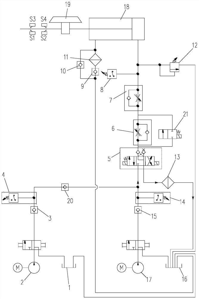
[0032] The specific embodiment of the present invention will be further described below in conjunction with accompanying drawing:

[0033] Such as figure 1 As shown, a rotary kiln retaining wheel hydraulic system according to the present invention includes an oil tank A1, a gear pump 2, a one-way valve-3, a pressure switch-4, an electromagnetic reversing valve-5, a one-way throttle valve-6, One-way throttle valve two 7, pressure switch two 8, one-way valve two 9, one-way valve three 10, filter one 11, overflow valve 12, filter two 13, pressure switch three 14, one-way valve four 15 , oil tank B16, small flow high-pressure pump 17, retaining wheel oil cylinder 18, one-way valve five 20, electromagnetic reversing valve two 21; The cavity is connected to the fuel tank B16 through the oil inlet main oil circuit, the rod chamber of the gear cylinder 18 is connected to the fuel tank B16 through the oil return main oil circuit, and the fuel tank A1 is connected to the fuel tank B16 ...


PUM


Abstract

The invention relates to a rotary kiln catch wheel hydraulic system and a working method thereof. The system comprises an oil tank A, a gear pump, a first one-way valve, a first pressure switch, a first electromagnetic directional valve, a first one-way throttle valve, a second one-way throttle valve, a second pressure switch, a second one-way valve, a third one-way valve, a first filter, an overflow valve, a second filter, a third pressure switch, a fourth one-way valve, an oil tank B, a small-flow high-pressure pump, a catch wheel oil cylinder, a fifth one-way valve and a second electromagnetic directional valve. The rotary kiln catch wheel hydraulic system and the working method thereof aim to shorten the oil supplementing time of the catch wheel hydraulic system, and the adjusting result of the throttle valves is not damaged in the oil supplementing process; and in addition, the hydraulic system is used for monitoring the stress state of a rotary kiln during running, key components of the rotary kiln are effectively protected, and the service life of the rotary kiln is prolonged.

Description

technical field [0001] The invention relates to the technical field of rotary kiln, in particular to a rotary kiln retaining wheel hydraulic system and a working method thereof capable of realizing fast refueling and safety protection functions. Background technique [0002] The rotary kiln is a widely used thermal kiln. Its working principle is: through the motor and transmission device, the cylinder is driven to roll continuously on the supporting wheel, so that the material moves from the high end to the low end of the rotary kiln. If the relative position of the rolling ring and the supporting wheel of the rotary kiln remains unchanged, grooves will be formed on the supporting wheel due to wear, which will affect the operation of the rotary kiln and increase the rotational resistance. [0003] Large-scale rotary kilns are generally equipped with a retaining wheel to cooperate with the thrust wheel to push the wheel to move up and down on the supporting wheel, so as to av...

Claims


Application Information

Patent Timeline
Patent Type & Authority Applications(China)
IPC IPC(8): F15B21/08F15B11/042F15B11/08F15B13/04F15B15/14F15B19/00F15B20/00F27B7/22F27B7/42
CPCF15B11/042F15B11/08F15B13/0401F15B15/1423F15B15/149F15B19/00F15B20/005F15B20/007F15B21/005F15B21/087F27B7/22F27B7/42
Inventor 徐大鹏崔学文刘爽刘淳李根
Owner ACRE COKING & REFRACTORY ENG CONSULTING CORP DALIAN MCC
Why Eureka
Try Eureka