A test system and test method for motion response test of a deep-sea operating platform

A motion response, working platform technology, applied in fluid dynamics test, machine/structural component testing, measuring device, etc., can solve the problems of poor real-time data acquisition, high test model requirements, high test cost, etc., to reduce design The effect of difficulty and test cost, compact structure and convenient operation

Active Publication Date: 2022-05-17
CHINA SHIP SCIENTIFIC RESEARCH CENTER (THE 702 INSTITUTE OF CHINA SHIPBUILDING INDUSTRY CORPORATION)
View PDF5 Cites 0 Cited by
  • Summary
  • Abstract
  • Description
  • Claims
  • Application Information

AI Technical Summary

Problems solved by technology

Traditional submarine hydrodynamic tests mainly include constrained model tests and self-propulsion model tests; the constrained model tests are based on the mature six-free motion equations of submarines as the theoretical basis, and the model hydrodynamics and its coefficients are measured, which cannot directly reflect the motion response of deep-sea operating platforms , and because there is no mature theoretical model for motion response prediction under deep-sea operating conditions, the measurement results of the constraint model test cannot be well applied to the motion response prediction, and the application of the traditional constraint model test is limited; while the maneuverable self-propulsion model test is carried out to simulate the deep sea Operating conditions require the model to be capable of simulating underwater lifting, cable laying, construction and other operating scenarios. The requirements for the test model are high, and the test cost is high. At the same time, there are poor real-time data collection, underwater interference or environmental load control and monitoring, etc. difficulty

Method used


Image

  • A test system and test method for motion response test of a deep-sea operating platform
  • A test system and test method for motion response test of a deep-sea operating platform
  • A test system and test method for motion response test of a deep-sea operating platform

Examples


Embodiment Construction

[0038] The specific implementation manner of the present invention will be described below in conjunction with the accompanying drawings.

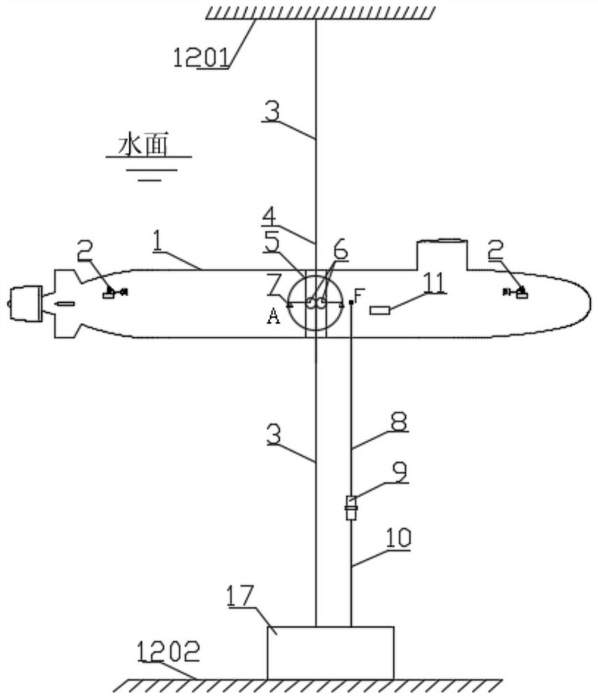
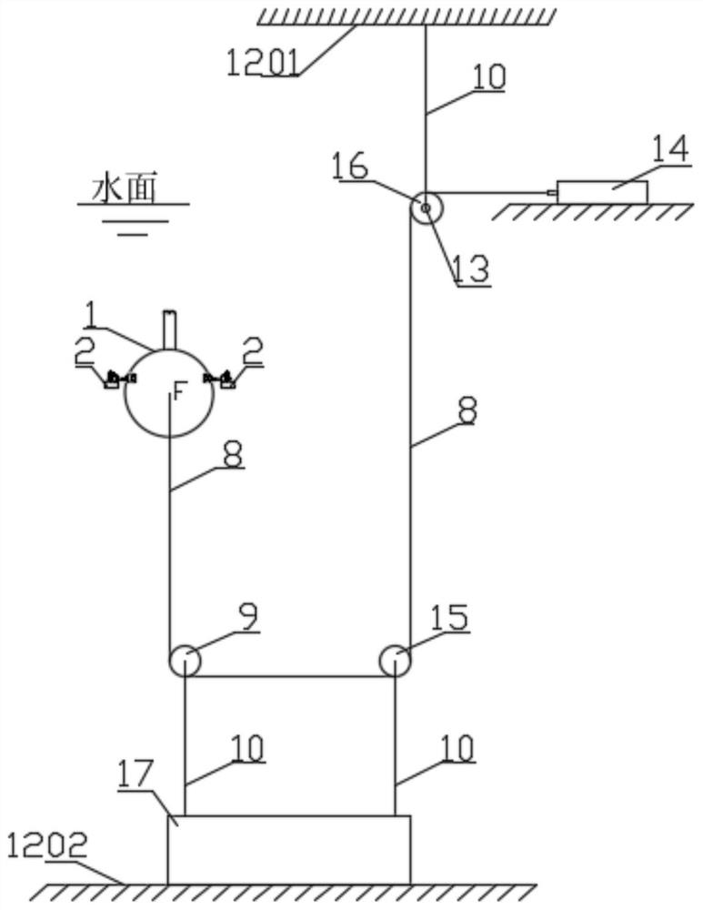
[0039] Such as Figure 1-Figure 3 As shown, the deep-sea operation platform motion response test system of this embodiment includes an upper wall 1201 above the water surface and a lower wall 1202 below the water surface,

[0040] The lower wall 1202 is provided with a weight 17,

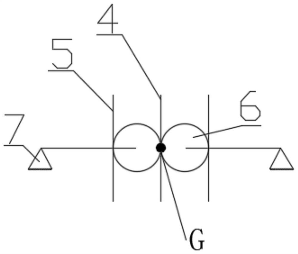
[0041] Also includes the underwater platform test model 1, the underwater platform test model 1 is equipped with a plurality of auxiliary thrusters 2, the interior of the underwater platform test model 1 is provided with an inclinometer 11, and the middle part of the underwater platform test model 1 is provided with a The underwater platform test model 1 at the hole 5 and the through hole 5 are symmetrically provided with support seats 7, and the inner sides of the two support seats 7 are equipped with rollers 6 through connecting rods, and the two rollers 6 ar...


PUM


Abstract

The invention relates to a motion response test system and a test method for a deep-sea operating platform, comprising an underwater platform test model, a steel wire rope, a roller and its support base, a pulley and its support rod, a displacement sensor, a trim meter, and a pin-shaft force sensor. And control the motor and other components. Realize the simulation and application of environmental loads such as deep-sea lifting, cable laying, ocean current or internal waves, and directly simulate deep-sea operation scenarios without underwater platform tests, which effectively reduces the difficulty of underwater platform test design and test costs; on the basis of load simulation application , Through the combination of wire rope and roller, the free heave and pitch of the underwater platform test model is realized while restricting the movement in other directions, and the displacement sensor and pitch meter are used to measure the motion response in real time. It has simple structure, reliable operation and convenient installation, and provides a new method and new means for the research on motion response prediction of deep-sea operations.

Description

technical field [0001] The invention relates to the technical field of test systems, in particular to a test system and a test method for a motion response test of a deep-sea operation platform. Background technique [0002] The deep-sea operation platform hovers underwater, and uses the cable-controlled submersible (ROV), underwater cranes and other equipment to carry out underwater lifting, underwater cable laying, underwater construction maintenance, repairs and other operations in the deep sea. The impact of sea waves and strong concealment can effectively take advantage of manned / unmanned collaborative detection operations. At this time, the operating device-umbilical cable-underwater platform forms a cable-connected multi-body coupling system, and the hovering state of the underwater platform is in a state of micro-restoration force. Large operating disturbances or external environmental loads cause the platform to heave or pitch. , thereby affecting the safety of the...

Claims


Application Information

Patent Timeline
Patent Type & Authority Patents(China)
IPC IPC(8): G01M10/00
CPCG01M10/00
Inventor 周念福冯康佳张亦驰渠继东
Owner CHINA SHIP SCIENTIFIC RESEARCH CENTER (THE 702 INSTITUTE OF CHINA SHIPBUILDING INDUSTRY CORPORATION)
Why Eureka
Try Eureka