
Overhead conductor current-carrying capacity calculation method and device and terminal equipment,

A technology of overhead wires and calculation methods, applied in the direction of measuring devices, measuring electricity, and measuring electrical variables, etc., can solve problems such as inaccurate calculation results, dependence on cleanliness, and large value errors, and achieve low implementation difficulty and systematic Good stability and low cost

Active Publication Date: 2021-06-22
ELECTRIC POWER RES INST OF GUANGDONG POWER GRID
View PDF8 Cites 3 Cited by
  • Summary
  • Abstract
  • Description
  • Claims
  • Application Information

AI Technical Summary

Problems solved by technology

There are usually two methods for the value of the actual overhead wire dynamic capacity increase sunshine intensity: the first is to use an additional solar radiation sensor for real-time monitoring; but this method is too dependent on the sensor installation angle and the cleanness of the surface, once installed If the angle is wrong or there is dust on the surface, the measurement will be inaccurate; the second is to use information such as time and the latitude of the location of the overhead wire to determine the intensity of solar radiation
However, this method is only suitable for sunny days and good atmospheric visibility. When it is cloudy or the atmospheric visibility is poor, the value error will be too large, and the calculation results will also be inaccurate.

Method used


Image

  • Overhead conductor current-carrying capacity calculation method and device and terminal equipment,
  • Overhead conductor current-carrying capacity calculation method and device and terminal equipment,
  • Overhead conductor current-carrying capacity calculation method and device and terminal equipment,

Examples


Embodiment Construction

[0051] The following will clearly and completely describe the technical solutions in the embodiments of the present invention with reference to the accompanying drawings in the embodiments of the present invention. Obviously, the described embodiments are only some, not all, embodiments of the present invention. Based on the embodiments of the present invention, all other embodiments obtained by persons of ordinary skill in the art without creative efforts fall within the protection scope of the present invention.

[0052] It should be understood that the step numbers used herein are only for convenience of description, and are not intended to limit the execution order of the steps.

[0053] It should be understood that the terminology used in the description of the present invention is for the purpose of describing particular embodiments only and is not intended to limit the present invention. As used in this specification and the appended claims, the singular forms "a", "an"...


PUM


Abstract

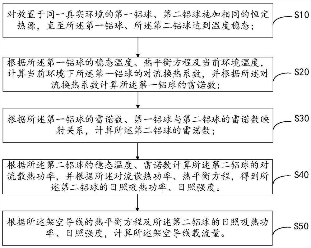
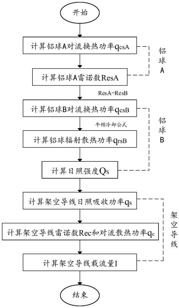
The invention discloses an overhead conductor current-carrying capacity calculation method and device and terminal equipment, and the method comprises the steps: applying a same constant heat source to a first aluminum ball and a second aluminum ball which are placed in a same real environment until the first aluminum ball and the second aluminum ball reach a temperature steady state; according to the steady-state temperature of the first aluminum ball, the heat balance equation and the current environment temperature, calculating the convective heat transfer coefficient of the first aluminum ball in the current environment, and then calculating the Reynolds number of the first aluminum ball; calculating the Reynolds number of the second aluminum ball according to the Reynolds number of the first aluminum ball and the Reynolds number mapping relation between the first aluminum ball and the second aluminum ball; and calculating the convection heat dissipation power of the second aluminum ball according to the steady-state temperature and Reynolds number of the second aluminum ball, obtaining the sunlight heat absorption power and sunlight intensity of the second aluminum ball in combination with the heat balance equation of the second aluminum ball, and finally obtaining the current-carrying capacity of the overhead conductor in combination with the heat balance equation of the overhead conductor. The method provided by the invention has the advantages of accurate result, good stability, easy implementation and low cost.

Description

technical field [0001] The invention relates to the technical field of ampacity detection of electric overhead conductors, in particular to a calculation method, device and terminal equipment for the ampacity of overhead conductors. Background technique [0002] Usually, the calculation method of the ampacity of the overhead conductor is to monitor the climate model of the meteorological environment where the overhead conductor is located, and to monitor the wind speed, wind direction, sunshine, ambient temperature, etc. in real time, so as to calculate the corresponding ampacity of the overhead conductor under the environmental conditions; Among them, the heat production of overhead wires during operation includes the joule heat power of the current and the heat absorption power from sunlight. At present, most countries in the world regard the solar radiation intensity as a definite value in the selection of boundary conditions for the calculation of the carrying capacity o...

Claims


Application Information

Patent Timeline
IPC IPC(8): G01R31/00
CPCG01R31/00G01R31/003
Inventor 王锐骆书剑彭向阳杨翠茹余欣周刚
Owner ELECTRIC POWER RES INST OF GUANGDONG POWER GRID
Learn More