Novel bonding structure surface acoustic wave device and preparation method thereof

A surface acoustic wave device and bonding structure technology, applied in electrical components, impedance networks and other directions, can solve the problems of unsatisfactory bonding interface quality, device Q value decline, device performance deterioration, etc., to improve withstand power, The effect of improving quality and suppressing parasitic response

Active Publication Date: 2021-06-22
SHOULDER ELECTRONICS CO LTD
View PDF4 Cites 2 Cited by
  • Summary
  • Abstract
  • Description
  • Claims
  • Application Information

AI Technical Summary

Problems solved by technology

However, due to the different acoustic input impedance of the two materials, the acoustic reflection of the elastic wave at the bonding interface causes some parasitic responses, resulting in deterioration of device performance
In addition, due to the different lattice structures and thermal expansion coefficients of the two materials, the quality of the bonding interface is not ideal, which will also lead to a decrease in the Q value of the device

Method used


Image

  • Novel bonding structure surface acoustic wave device and preparation method thereof
  • Novel bonding structure surface acoustic wave device and preparation method thereof
  • Novel bonding structure surface acoustic wave device and preparation method thereof

Examples


Embodiment 1

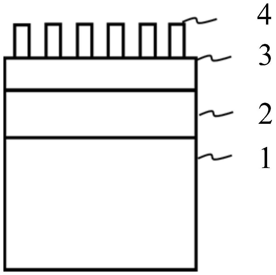
[0037] A new bonded structure surface acoustic wave device, the schematic diagram of its structure is shown in figure 1 As shown, it includes a support substrate 1, a composition graded layer 2, a piezoelectric substrate 3, and an interdigital transducer 4 from bottom to top. The composition graded layer 2 is used to provide total reflection of sound waves, and the composition graded layer 2 is close to The sound velocity of the components on the substrate side is higher than that on the side close to the piezoelectric substrate 3, and the components change linearly along the growth direction.

[0038] Specifically, the composition of the graded composition layer 2 near the substrate is Si 3 N 4 , the intermediate component is SiO x N 1-x , the composition near the piezoelectric substrate 3 side is SiO 2 , where 03 N 4 The sound velocity of the components is higher than that of SiO 2 The sound velocity of the component, the acoustic impedance of the acoustic wave of the ...

Embodiment 2

[0055] A new bonded structure surface acoustic wave device, the schematic diagram of its structure is shown in figure 1 As shown, it includes a support substrate 1, a composition graded layer 2, a piezoelectric substrate 3, and an interdigital transducer 4 from bottom to top. The composition graded layer 2 is used to provide total reflection of sound waves, and the composition graded layer 2 is close to The sound velocity of the components on the substrate side is higher than that on the side close to the piezoelectric substrate 3, and the components change linearly along the growth direction.

[0056] Specifically, the composition of the graded composition layer 2 near the substrate is AlN, and the middle composition is Al x Ga 1-x N. The component near the piezoelectric substrate 3 is GaN, where 0x Ga 1-x The Al composition of N gradually decreases linearly along the growth direction, the Ga composition gradually increases linearly along the growth direction, and Al x Ga ...


PUM


Abstract

The invention discloses a novel bonding structure surface acoustic wave device and a preparation method thereof, and relates to the field of surface acoustic wave devices. The novel bonding structure surface acoustic wave device comprises a supporting substrate, a component gradient layer, a piezoelectric substrate and an interdigital transducer from bottom to top in sequence. The component gradient layer is used for providing total reflection of sound waves, the component sound velocity of the side, close to the substrate, of the component gradient layer is higher than that of the side, close to the piezoelectric substrate, of the component gradient layer, and components linearly change in the growth direction. The component gradient layer can inhibit generation of parasitic response, can also improve the quality of the bonding film and improve the electromechanical coupling coefficient and tolerance power of the device, and the preparation method is relatively mature and simple.

Description

technical field [0001] The invention relates to the field of acoustic surface devices, in particular to a novel bonding structure surface acoustic wave device and a preparation method thereof. Background technique [0002] Surface acoustic wave devices are widely used in the field of mobile terminals due to their miniaturization and low insertion loss. Currently, the most commonly used piezoelectric material is LiTaO 3 and LiNbO 3 , its strong piezoelectric performance enables the surface acoustic wave filter device to obtain a relatively large relative bandwidth, which is very suitable for the technical needs of 5G communication. [0003] But LiTaO 3 and LiNbO 3 Fundamental surface acoustic wave devices have a serious problem of frequency drift with temperature, which limits the application range of this type of device. At present, the bonding technology of piezoelectric substrate and low-temperature drift substrate can effectively reduce the frequency temperature coeff...

Claims


Application Information

Patent Timeline
Patent Type & Authority Applications(China)
IPC IPC(8): H03H3/02H03H9/02
CPCH03H3/02H03H9/02H03H2003/023Y02P70/50
Inventor 封琼许志斌傅肃磊陆增天
Owner SHOULDER ELECTRONICS CO LTD
Why Eureka
Try Eureka