Staggered mutual anchoring connecting structure for prefabricated shear walls and vertical joints at edge members

A technology of prefabricated shear and edge components, applied in the direction of building components, walls, building structures, etc., can solve the problems of limiting the size of prefabricated shear walls, complex connection structure, long vertical joint length, etc., to achieve Achieve vertical hoisting operations, improve assembly efficiency, reduce use and on-site construction effects

Inactive Publication Date: 2021-06-25
CHINA CONSTR FIFTH ENG DIV CORP LTD
View PDF7 Cites 1 Cited by
  • Summary
  • Abstract
  • Description
  • Claims
  • Application Information

AI Technical Summary

Problems solved by technology

[0003] The structure of this connection method is relatively complicated. Not only does it need to add connecting steel bars on the construction site, resulting in an increase in the amount of steel bars, but also requires a long vertical joint length, and there are many wet operations on site, which limits the demolition of prefabricated shear walls. size

Method used


Image

  • Staggered mutual anchoring connecting structure for prefabricated shear walls and vertical joints at edge members
  • Staggered mutual anchoring connecting structure for prefabricated shear walls and vertical joints at edge members
  • Staggered mutual anchoring connecting structure for prefabricated shear walls and vertical joints at edge members

Examples


Embodiment 1

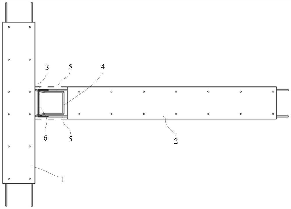
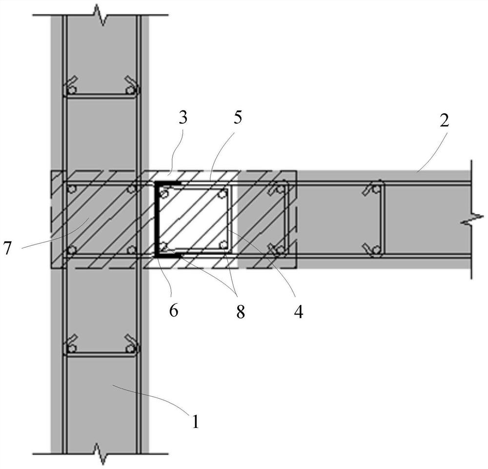
[0044] refer to Figure 1-3 , the embodiment of the present application discloses a prefabricated shear wall edge member vertical joint dislocation mutual anchor connection structure, including: the first prefabricated shear wall 1, the second prefabricated shear wall 2 and the edge member 7, the first prefabricated shear wall A vertical joint 3 is formed between the shear wall 1 and the second prefabricated shear wall 2; the edge member 7 includes a prefabricated part and a cast-in-place part; the prefabricated part at least includes a first part prefabricated in the first prefabricated The joint 3 is located in the edge member 7 and forms a cast-in-place part; the edge member 7 has a number of stirrups 4; the second prefabricated shear wall 2 has a number of horizontal reinforcement bars 5; the stirrups 4 and the horizontal reinforcement bars 5 are all extended into the vertical joint In the seam, and staggered and anchored to each other in the vertical direction.

[0045] ...

Embodiment 2

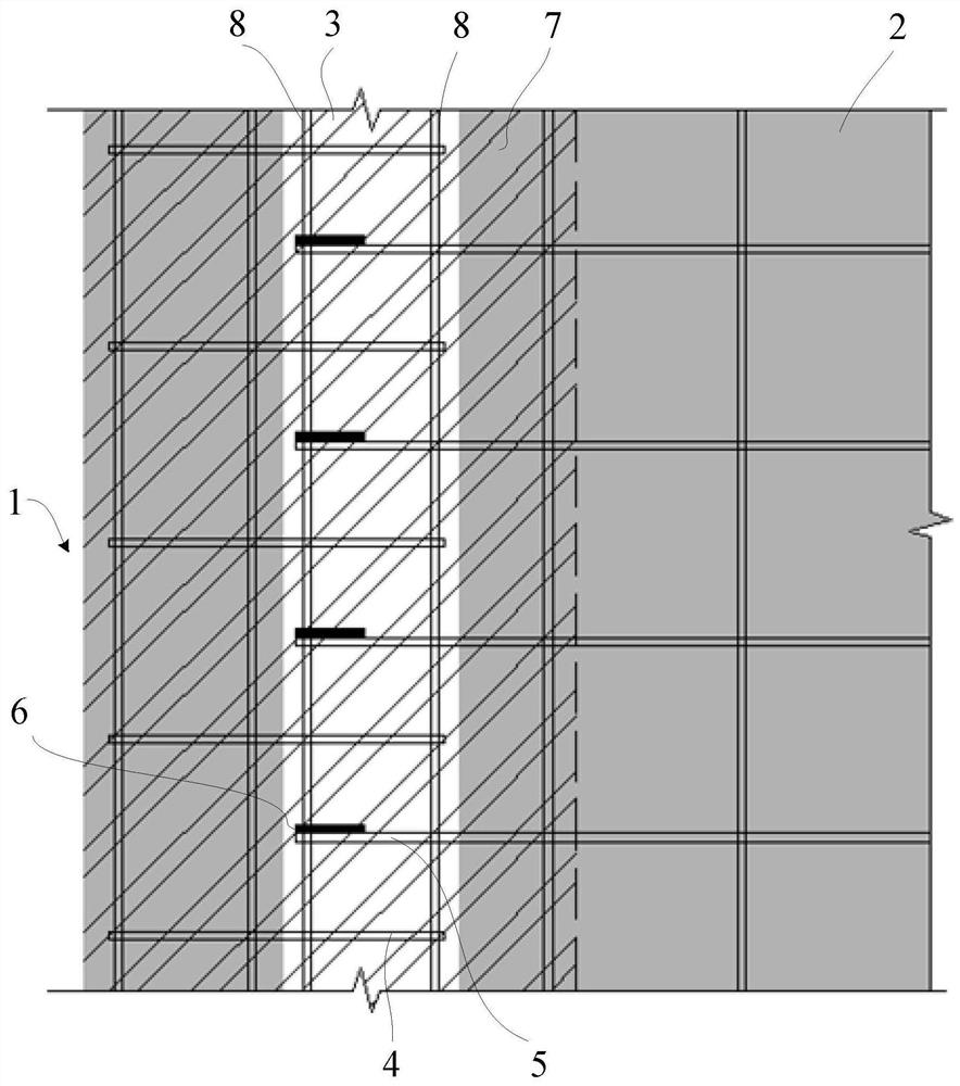
[0056] see Figure 7 The difference between this embodiment and Embodiment 1 is that the first part of the edge member 7 located in the middle of the first prefabricated shear wall 1 is anchored with stirrups, and the stirrups are in a semi-enclosed structure, such as U-shaped, wherein the stirrups The closed end is anchored into the first part of the first prefabricated shear wall 1 (that is, the prefabricated part of the edge member), and the open end includes two parallel steel bars to form a horizontal steel bar 5. The horizontal steel bar 5 is opposite to the first prefabricated shear wall 1. The wall surface extends outwards and extends into the vertical joint 3; the part of the horizontal steel bar 5 located in the first prefabricated shear wall 1 is bound and fixed with the longitudinal steel bar of the edge member (welding or other methods are included in other solutions). The second prefabricated shear wall 2 is a prefabricated concrete shear wall panel with a double...


PUM


Abstract

The invention discloses a staggered mutual anchoring connecting structure for prefabricated shear walls and vertical joints at edge members. The staggered mutual anchoring connecting structure comprises two prefabricated shear walls and the vertical joints at the edge members, wherein steel bars are reserved in the prefabricated shear walls and are anchored into the vertical joints at the edge members in a staggered mode, U-shaped stirrups are bound on site, the stirrups are closed, longitudinal steel bars are placed, and finally, the vertical joints are poured through composite materials such as ultrahigh-performance concrete, high-performance concrete, steel fiber reinforced concrete, reactive powder concrete and ECC, so that the connection of the prefabricated shear walls and the edge members is completed. According to the staggered mutual anchoring connecting structure of the scheme, the steel bars at the prefabricated shear wall and the edge members are directly anchored into a post-pouring area, so that additional connecting steel bars at the inner edge members of wallboards of the prefabricated shear walls are omitted, and the required length of the vertical joints is small; the prefabricated shear walls are flexible to disassemble, and standardized production of a prefabricated building is facilitated; and the technical problems of complexity in connection of an existing assembly type shear wall and the vertical joints at the edge members and more on-site wet operation are solved.

Description

technical field [0001] The present application relates to the field of prefabricated wall connection structures, in particular to a vertical joint dislocation mutual anchor connection structure at edge components of prefabricated shear walls. Background technique [0002] In the current prefabricated shear wall structure, when connecting the vertical joints at the edge members of the prefabricated shear wall, the connecting reinforcement is usually added in the area where the prefabricated shear wall is connected by artificial addition at the construction site, and then Connect the connecting reinforcement with the horizontal reinforcement protruding from the prefabricated shear wall on the other side, and finally pour concrete into the vertical joint to realize the vertical joint connection at the edge components of the prefabricated shear wall. [0003] The structure of this connection method is relatively complicated. Not only does it need to add connecting steel bars on ...

Claims


Application Information

Patent Timeline
Patent Type & Authority Applications(China)
IPC IPC(8): E04B2/00E04B1/41E04B1/38E04G21/14
CPCE04B2/00E04B1/41E04B1/38E04G21/14Y02A30/30
Inventor 周泉姚延化李水生唐宇轩
Owner CHINA CONSTR FIFTH ENG DIV CORP LTD
Why Eureka
Try Eureka