A liquefied gas classification purification device

A technology of liquefied gas and liquefied tanks, which is applied in the field of liquefied gas classification and purification devices, can solve the problems of starting and stopping of vacuum pumps, affecting the service life of vacuum pumps, instability of raw material tanks and liquefaction tanks, etc., and achieves rapid vacuuming and liquefaction And good purification effect, good cooling effect

Active Publication Date: 2022-02-22
无锡恒大电子科技有限公司
View PDF16 Cites 0 Cited by
  • Summary
  • Abstract
  • Description
  • Claims
  • Application Information

AI Technical Summary

Problems solved by technology

[0002] During the transportation of gas, due to the large volume of the gas, it will occupy a large volume during the transportation of the gas, and the transportation efficiency is low. Therefore, the liquefaction and purification of the gas can greatly improve the efficiency of gas transportation, and at the same time , improve the purity of the gas, but when the existing gas liquefaction and purification equipment is used to liquefy and purify the gas, it usually purifies the gas raw material containing impurities through the purification equipment, and then uses low temperature to liquefy the purified gas, but , the existing purification device has the following problems in use:
[0003] 1. Commonly used gas cooling methods usually use liquid nitrogen to cool down. When the raw material tank and liquefaction tank are placed in liquid nitrogen, on the one hand, the placed raw material tank and liquefaction tank will shake and become unstable. On the other hand, In order to facilitate the placement of raw material tanks and liquefaction tanks, the sealing performance of liquid nitrogen will be reduced and the liquefaction effect will be affected;
[0004] 2. When vacuuming the raw material tanks, liquefaction tanks and purification tanks, vacuum pumps are usually used for vacuum pumping. This method will cause the vacuum pumps to start and stop frequently, affecting the service life of the vacuum pumps. Moreover, after purification The impurity gas cannot be handled well;

Method used


Image

  • A liquefied gas classification purification device
  • A liquefied gas classification purification device
  • A liquefied gas classification purification device

Examples


Embodiment

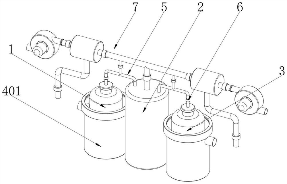
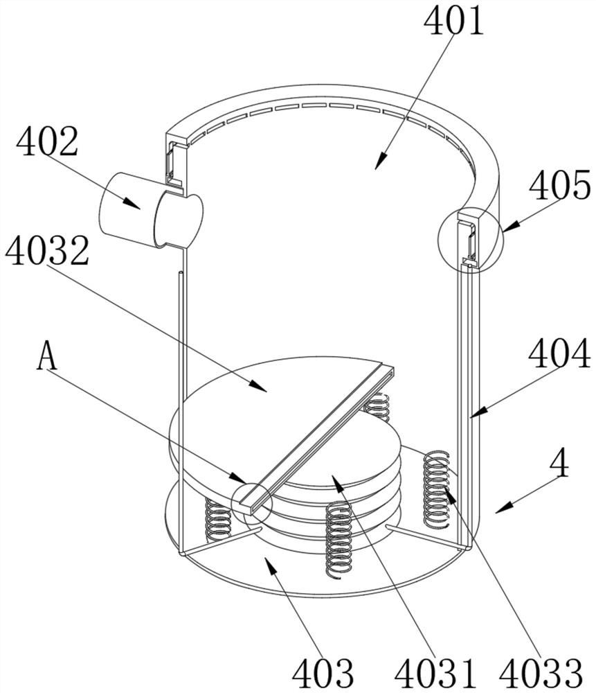
[0038] Example: such as Figure 1~6 As shown, a liquefied gas classification purification device, the purification device includes a raw material tank 1, a purification tank 2, a liquefaction tank 3, a cooling device 4, a first connecting pipe 5, a first electromagnetic valve 6 and a vacuum device 7;

[0039] One side of the purification tank 2 is provided with a raw material tank 1, and the other side of the purification tank 2 is provided with a liquefaction tank 3. The purification tank 2 is used to purify the gas inside the raw material tank 1, remove impurity gases, and liquefy the purified gas Stored in the liquefaction tank 3, both the raw material tank 1 and the liquefaction tank 3 are cooled by the cooling device 4, and the cooling device 4 is used to cool the raw material tank 1 to remove impurity gases, so that impurities with high boiling points can be vaporized, and then removed For impurity gas, the cooling device 4 is used to lower the temperature of the liquefa...


PUM


Abstract

The invention discloses a classification and purification device for liquefied gas, which belongs to the technical field of gas purification and comprises a purification tank. A raw material tank is arranged on one side of the purification tank, and a liquefaction tank is arranged on the other side of the purification tank. The raw material tank and the The temperature of the liquefaction tank is lowered by the cooling device, and the raw material tank and the purification tank and between the liquefaction tank and the purification tank are connected by the first connecting pipe. The device, the placed raw material tank and liquefaction tank can squeeze the supporting bellows, so that the extruded gas is transported to the inside of the communication cavity through the gas delivery hose, and the gas pushes the sealing plate to slide inside the storage groove and the limit groove. The sealing plate slides out of the limit groove under the push of the gas, and seals the gap between the cooling barrel, the raw material tank and the liquefaction tank, so that the cooling effect of liquid nitrogen is better, and the effect of liquefaction and purification of gas is improved. better.

Description

technical field [0001] The invention relates to the technical field of gas purification, in particular to a liquefied gas classification purification device. Background technique [0002] During the transportation of gas, due to the large volume of the gas, it will occupy a large volume during the transportation of the gas, and the transportation efficiency is low. Therefore, the liquefaction and purification of the gas can greatly improve the efficiency of gas transportation, and at the same time , improve the purity of the gas, but when the existing gas liquefaction and purification equipment is used to liquefy and purify the gas, it usually purifies the gas raw material containing impurities through the purification equipment, and then uses low temperature to liquefy the purified gas, but , the existing purification device has the following problems in use: [0003] 1. Commonly used gas cooling methods usually use liquid nitrogen to cool down. When the raw material tank ...

Claims


Application Information

Patent Timeline
Patent Type & Authority Patents(China)
IPC IPC(8): B01D5/00F16F15/06F16F15/04
CPCB01D5/0006F16F15/06F16F15/04
Inventor 王敏孙珏李鹏昊
Owner 无锡恒大电子科技有限公司
Why Eureka
Try Eureka