
UV paint coating waste gas treatment system

A technology for waste gas treatment and painting, applied in gas treatment, combined devices, membrane technology, etc., can solve problems such as high operating costs, increased energy consumption, waste water discharge, etc., to reduce the process of repeated accumulation, reduce the frequency of cleaning, The effect of preventing dripping phenomenon

Active Publication Date: 2021-06-29
厦门爱迪特环保科技有限公司
View PDF6 Cites 0 Cited by
  • Summary
  • Abstract
  • Description
  • Claims
  • Application Information

AI Technical Summary

Problems solved by technology

[0003] The wet process generally adopts water washing and absorption methods such as swirling plate towers, and partially intercepts the paint residue particles through water washing, and then intercepts and removes the water mist particles with a dry filter. The disadvantage is that the circulating water needs to be replaced every day. It brings a lot of wastewater discharge problems, and at the same time, because of the water washing to increase the humidity of the exhaust gas, it brings about the problem of a decrease in the purification efficiency of the subsequent treatment process and an increase in energy consumption.
[0004] The dry process generally adopts multi-stage dry filter filtration method. The disadvantage is that the filter needs to be replaced frequently. For the working condition with a large amount of paint spraying, the filter needs to be replaced in less than 2 hours, otherwise normal production will not be possible; not only brings Due to the high operating costs and the impact on production, how to pretreat the exhaust gas from painting to reduce the paint slag particles in the exhaust gas has become a top priority

Method used


Image

  • UV paint coating waste gas treatment system
  • UV paint coating waste gas treatment system
  • UV paint coating waste gas treatment system

Examples


Embodiment Construction

[0042] In order to make the technical problems, technical solutions and beneficial effects to be solved by the present invention clearer and clearer, the present invention will be further described in detail below in conjunction with the accompanying drawings and embodiments. It should be understood that the specific embodiments described here are only used to explain the present invention, not to limit the present invention.

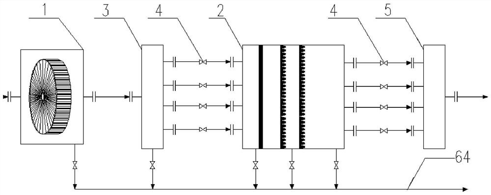
[0043] see figure 1, an exhaust gas pretreatment system containing UV paint coating, including a centrifuge 1 and a multi-stage filter channel 2, the air outlet end of the centrifuge 1 is connected to the air inlet of the multi-stage filter channel 2 through an air distribution box 3 and a switch valve 4 , the air outlet of the multi-stage filter channel 2 discharges the treated gas through the switch valve 4 or mixes it through the air mixing box 5 and then connects to other equipment.

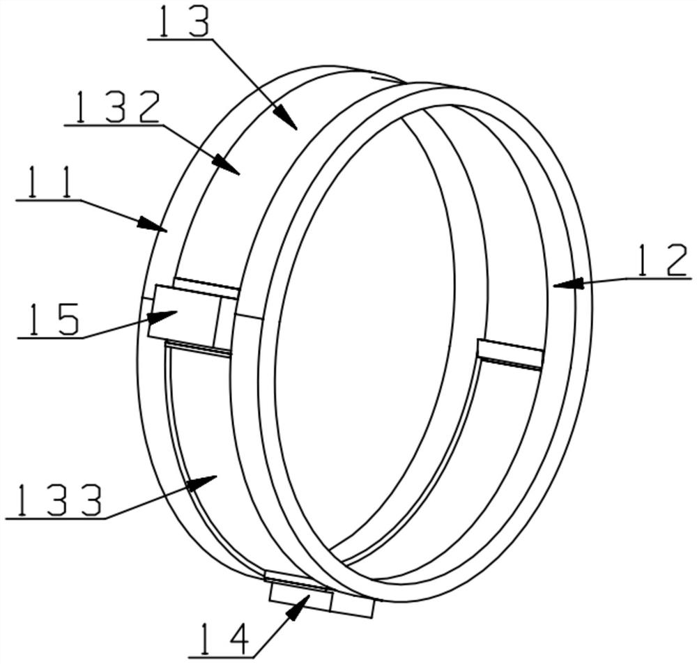
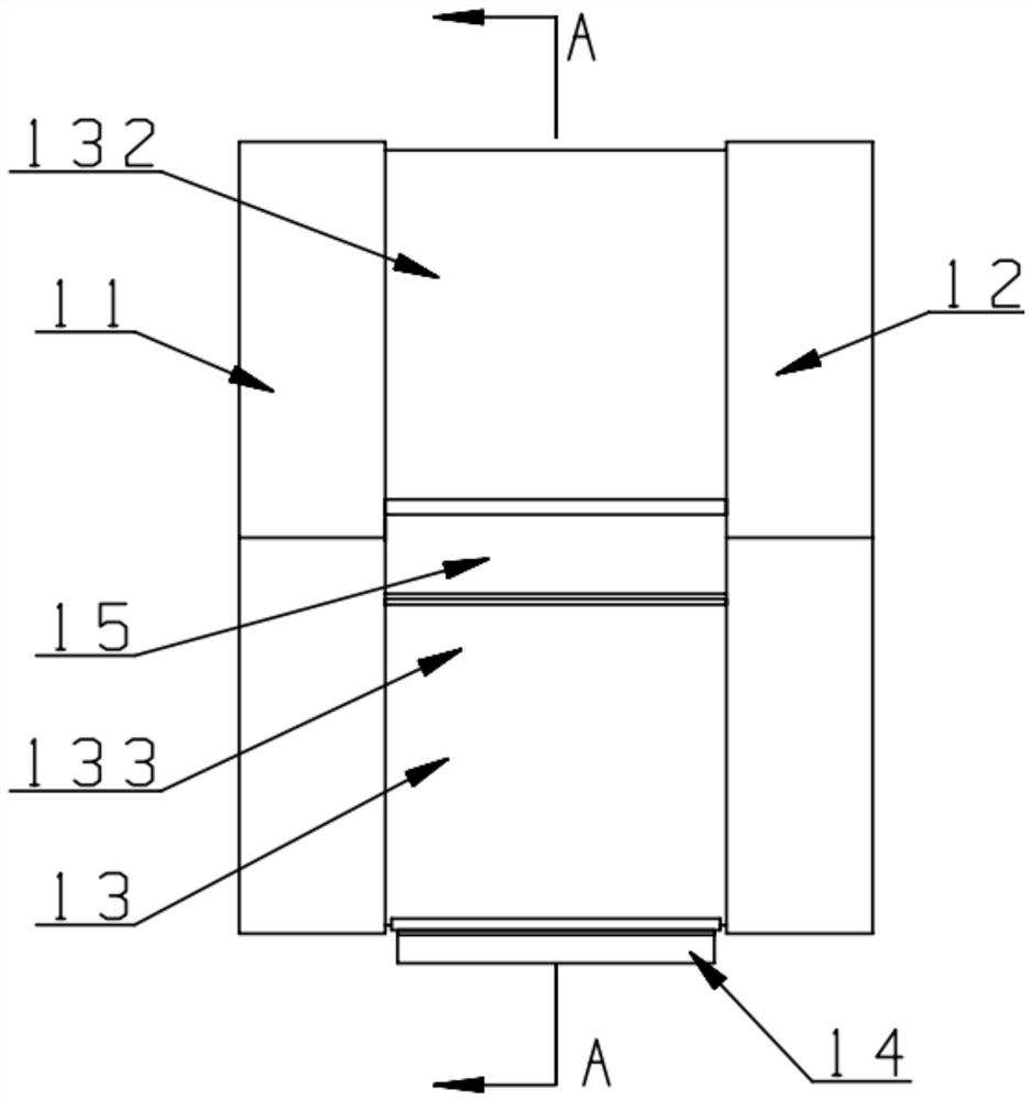
[0044] combine Figure 2-Figure 5 As shown, the centrifuge 1 in...


PUM


Abstract

The invention provides a UV paint coating waste gas treatment system which comprises a centrifugal machine and a multi-stage filtering channel, wherein the air outlet end of the centrifugal machine is connected with an air inlet of the multi-stage filtering channel through a switch valve. The centrifugal machine comprises a shell, the shell comprises a centrifugal cover, the cross section of the centrifugal cover is oval, a long shaft of the centrifugal cover is vertically arranged, and a short shaft of the centrifugal cover is horizontally arranged. By arranging the oval centrifugal cover, the gradient of the top of the oval centrifugal cover is larger than that of a traditional round cover and is close to a cone, paint slag particle fluid gathered on the top can completely slide down, the dripping phenomenon is reduced or even completely prevented, accumulation of paint slag particles on a motor or a motor shell and components of the motor is reduced, the cleaning frequency of the centrifugal machine is reduced, and meanwhile the paint slag particles are prevented from dripping on the rotating impeller, the repeated gathering process of the paint slag particles is reduced, and the centrifugal efficiency is improved.

Description

technical field [0001] The invention relates to a waste gas treatment system for painting containing UV paint. Background technique [0002] At present, there are two types of coating exhaust gas treatment technologies, one is wet process and the other is dry process. [0003] The wet process generally adopts water washing and absorption methods such as swirling plate towers, and partially intercepts the paint residue particles through water washing, and then intercepts and removes the water mist particles by a dry filter. The disadvantage is that the circulating water needs to be replaced every day. It brings a lot of wastewater discharge problems, and at the same time, because of the water washing to increase the humidity of the exhaust gas, it brings about the problem of a decrease in the purification efficiency of the subsequent treatment process and an increase in energy consumption. [0004] The dry process generally adopts multi-stage dry filter filtration method. Th...

Claims


Application Information

Patent Timeline
IPC IPC(8): B01D50/00B01D53/00
CPCB01D53/007B01D2258/0258B01D2259/804B01D50/10B01D50/20
Inventor 杨再华雷强张新煌张波倪张进薛枫黄桂宝陈恒云
Owner 厦门爱迪特环保科技有限公司
Learn More